
Operating instructions


7BOC Smootharc Advance II MIG 250C Operating manual
2.0 MIG Process
2.1 Introduction to Metal Inert Gas (MIG)
MIG welding embraces a group of arc welding processes in which a
continuous electrode (the wire) is fed by powered feed rolls (wire
feeder) into the weld pool. An electric arc is created between the tip of
the wire and the weld pool. The wire is progressively melted at the same
speed at which it is being fed and forms part of the weld pool. Both the
arc and the weld pool are protected from atmospheric contamination by
a shield of inert (non-reactive) gas, which is delivered through a nozzle
that is concentric with the welding wire guide tube.
Operation
MIG welding is usually carried out with a handheld torch as a semi-
automatic process. The MIG process can be suited to a variety of job
requirements by choosing the correct shielding gas, electrode (wire) size
and welding parameters. Welding parameters include the voltage, travel
speed, arc (stick-out) length and wire feed rate. The arc voltage and wire
feed rate will determine the ller metal transfer method.
This application combines the advantages of continuity, speed,
comparative freedom from distortion and the reliability of automatic
welding with the versatility and control of manual welding. The process
is also suitable for mechanised set-ups, and its use in this respect
isincreasing.
MIG welding can be carried out using solid wire, ux cored, or a copper-
coated solid wire electrode. The shielding gas or gas mixture may consist
of the following:
→ Argon
→ Carbon dioxide
→ Argon and carbon dioxide mixtures
→ Argon mixtures with oxygen or helium mixtures
Each gas or gas mixture has specic advantages and limitations. Other
forms of MIG welding include using a ux-cored continuous electrode
and carbon dioxide shielding gas, or using self-shielding ux-cored wire,
requiring no shielding gas.
2.2 Introduction to Flux Cored
Arc Welding (FCAW)
How it Works
Flux-cored arc welding (FCAW) uses the heat generated by a DC electric
arc to fuse the metal in the joint area, the arc being struck between a
continuously fed consumable ller wire and the workpiece, melting both
the ller wire and the workpiece in the immediate vicinity. The entire arc
area is covered by a shielding gas, which protects the molten weld pool
from the atmosphere.
FCAW is a variant of the MIG process and while there are many common
features between the two processes, there are also several fundamental
dierences.
As with MIG, direct current power sources with constant voltage output
characteristics are normally employed to supply the welding current.
With ux-cored wires the terminal that the ller wire is connected
to depends on the specic product being used, some wires running
electrode positive, others running electrode negative. The work return
is then connected to the opposite terminal. It has also been found that
the output characteristics of the power source can have an eect on the
quality of the welds produced.
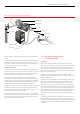
The wire feed unit takes the ller wire from a spool, and feeds it
through the welding torch, to the arc at a predetermined and accurately
controlled speed. Normally, special knurled feed rolls are used with ux-
cored wires to assist feeding and to prevent crushing the consumable.
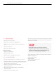
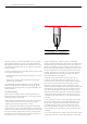
Typical MIG set up
Torch trigger
Welding wire
Weld
Weld pool
Torch
Shroud
Gas diuser
Contact tip
Shielding
Droplets