
Operating instructions
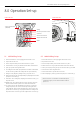

21BOC Smootharc Advance II MIG 250C Operating manual
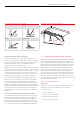
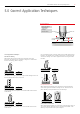
Recommended Electrode Angles for Fillet Welds
Multi-run horizontal llets have each run made using the same run
lengths (run length per electrode table). Each run is made in the same
direction, and care should be taken with the shape of each, so that it has
equal leg lengths and the contour of the completed llet weld
is slightly convex with no hollows in the face.
Vertical llet welds can be carried out using the upwards or downwards
technique. The characteristics of each are: upwards – current used is low,
penetration is good, surface is slightly convex and irregular. For multiple
run llets large single pass weaving runs can be used. Downwards –
current used is medium, penetration is poor, each run is small, concave
and smooth (only BOC Smootharc 13 is suitable for this position).
The downwards method should be used for making welds on thin
material only. Electrodes larger than 4.0 mm are not recommended
for vertical down welding. All strength joints in vertical plates 10.0
mm thick or more should be welded using the upward technique. This
method is used because of its good penetration and weld metal quality.
The rst run of a vertical up llet weld should be a straight sealing run
made with 3.15 mm or 4.0 mm diameter electrode. Subsequent runs
for large llets may be either numerous straight runs or several wide
weaving runs.
Correct selection of electrodes is important for vertical welding.
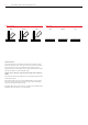
In overhead llet welds, careful attention to technique is necessary to
obtain a sound weld of good prole. Medium current is required for
best results. High current will cause undercutting and bad shape of
the weld, while low current will cause slag inclusions. To produce a
weld having good penetration and of good prole, a short arc length is
necessary. Angle of electrode for overhead llets is illustrated above.
3.8 Typical Defects Due to FaultyTechnique
Shielded metal arc welding, like other welding processes, has welding
procedure problems that may develop which can cause defects in the
weld. Some defects are caused by problems with the materials. Other
welding problems may not be foreseeable and may require immediate
corrective action. A poor welding technique and improper choice of
welding parameters can cause weld defects. Defects that can occur
when using the shielded metal arc welding process are slag inclusions,
wagon tracks, porosity, wormhole porosity, undercutting, lack of
fusion, overlapping, burn through, arc strikes, craters, and excessive
weld spatter. Many of these welding technique problems weaken the
weld and can cause cracking. Other problems that can occur which can
reduce the quality of the weld are arc blow, nger nailing, and improper
electrode coating moisture contents.
Defects caused by welding technique
Slag Inclusions
Slag inclusions occur when slag particles are trapped inside the weld
metal which produces a weaker weld. These can be caused by:
→ erratic travel speed
→ too wide a weaving motion
→ slag left on the previous weld pass
→ too large an electrode being used
→ letting slag run ahead of the arc.
Recommended Angles for Overhead Fillet Welds Recommended Electrode Angles for Fillet Welds
1st Run 2nd Run
Electrode
40°
55–60°
20–30°
1
2
3
4
5
6
Electrode
40°
55–60°
20–30°
1
2
3
4
5
6
3rd Run Multi-run Fillet
Electrode
40°
55–60°
20–30°
1
2
3
4
5
6
Electrode
40°
55–60°
20–30°
1
2
3
4
5
6
30˚
45˚
15˚