
Operating instructions

13BOC Smootharc Advance II MIG 250C Operating manual
Selection of the Correct Power Source
Power sources for MIG welding is selected on a number of dierent
criteria, including:
1 Maximum output of the machine
2 Duty cycle
3 Output control (voltage selection, wire feed speed control)
4 Portability
The following table gives an indication of the operating amperage for
dierent size wires.
Wire Size Amperage Range (A)
0.8 mm 60–180
0.9 mm 70–250
1.0 mm 90–280
1.2 mm 120–340
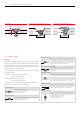
Selection of the Correct Polarity on the Power Source
Many power sources are tted with an optional reverse polarity dinse
connector.
To achieve the optimum welding it is important to adhere to the
consumable manufacturer's instruction to select the polarity.
As a general rule all solid and metal cored wires are welded on electrode
positive. (Work return lead tted to the negative connector.)
Some grades of self shielded ux cored wires (i.e. E71T-11, E71T-GS etc)
need to be welded on electrode negative. (Work return lead tted to the
positive connector.)
Selection of the Correct Shielding Gas
The selection of the shielding gas has a direct inuence on the
appearance and quality of the weldbead.
The thickness of the material to be welded will determine the type of
shielding gas that has to be selected. As a general rule the thicker the
material (C-Mn and Alloy steels) are the higher the percentage of CO
2
in
the shielding gas mixture.
Dierent grades of shielding are required for materials such as stainless
steel, aluminium and copper.
The following table gives an indication of the most common shielding
gases used for Carbon Manganese and alloy steel.
Material thickness Recommended shielding gas
1–8 mm Argoshield® Light
5–12 mm Argoshield® Universal
>12 mm Argoshield® Heavy
More detailed selection charts, including recommendations for welding
parameters (voltage, amperage, electrical stickout, travelspeed and
gasow rate) can be found in the following pages.