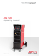
6PRRWKDUF $GYDQFH ,, MIG 250C Operating manual Machine comes with side tray
BOC Smootharc Advance II MIG 250C Operating manual Welcome to a better way of welding. This operating manual provides the basic knowledge required for MIG Welding, as well as highlighting important areas of how to operate the Smootharc ADVANCE machines. With normal use and by following these recommended steps, your Smootharc ADVANCE machine can provide you with years of troublefree service.
BOC Smootharc Advance II MIG 250C Operating manual Contents. 1.0 Recommended Safety Guidelines and Precautions 1.1 1.2 1.3 1.4 Health Hazard Information Personal Protection Electrical shock User Responsibility 4 2.0 MIG Process 7 5 5 6 6 2.1 Introduction to Metal Inert Gas (MIG) 2.2 Introduction to Flux Cored Arc Welding (FCAW) 2.3 Introduction to Metal Cored Arc Welding (MCAW) 2.4 Fundamentals of MIG, FCAW and MCAW 7 7 9 12 3.0 MMA Process 14 4.0 3.1 Introduction 3.2 Process 3.
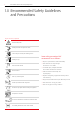
BOC Smootharc Advance II MIG 250C Operating manual 1.0 Recommended Safety Guidelines and Precautions Diagram and safety explanation Electrical safety alert Welding electrode causing electric shock Fumes and gases coming from welding process Welding arc rays Some safety precautions BOC recommends are as follows: →→ Repair or replace defective cables immediately. Read instruction manual Become trained Wear dry, insulated gloves →→ Never watch the arc except through lenses of the correct shade.
BOC Smootharc Advance II MIG 250C Operating manual 1.1 Health Hazard Information The actual process of MIG welding is one that can cause a variety of hazards. All appropriate safety equipment should be worn at all times, i.e. headwear, hand and body protection. Electrical equipment should be used in accordance with the manufacturer’s recommendations. →→ Fumes from the welding of some metals could have an adverse effect on your health. Don’t breathe them in.
1.3 BOC Smootharc Advance II MIG 250C Operating manual Electrical shock →→ Never touch ‘live’ electrical parts →→ Always repair or replace worn or damaged parts →→ Disconnect power source before performing any maintenance or service →→ Earth all work materials →→ Never work in moist or damp areas Avoid electric shock by: →→ Wearing dry insulated boots. →→ Wearing dry leather gloves. →→ Working on a dry insulated floor where possible. 1.
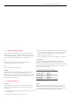
BOC Smootharc Advance II MIG 250C Operating manual 7 2.0 MIG Process Typical MIG set up Torch Torch trigger Shroud Gas diffuser Welding wire Weld Contact tip Shielding Droplets Weld pool 2.1 Introduction to Metal Inert Gas (MIG) MIG welding embraces a group of arc welding processes in which a continuous electrode (the wire) is fed by powered feed rolls (wire feeder) into the weld pool. An electric arc is created between the tip of the wire and the weld pool.
BOC Smootharc Advance II MIG 250C Operating manual Extended self shielded flux cored wire nozzle Unlike MIG, which uses a solid consumable filler wire, the consumable used in FCAW is of tubular construction, an outer metal sheath being filled with fluxing agents plus metal powder. The flux fill is also used to provide alloying, arc stability, slag cover, de-oxidation, and, with some wires, gas shielding.
BOC Smootharc Advance II MIG 250C Operating manual 9 Process Schematic Diagram for MIG / FCAW and MCAW Gas hose Continous wire Wire feed unit Power cable Gas cylinder Torch conduit Welding torch Arc Workpiece Earth clamp Power source Return cable efficiency differs by wire type and manufacturer it is typically between 75–85%. Flux cored arc welding does, however, have the same drawback as solid wire MIG in terms of gas disruption by wind, and screening is always necessary for site work.
BOC Smootharc Advance II MIG 250C Operating manual Schematic of Dip Transfer 1 2 3 4 5 6 Short circuit Necking Arc re-ignition Arc established Arc gap shortens Short circuit 1 2 3 4 5 6 Time Current (A) Voltage (V) Short circuit cycle Unlike MIG, which uses a solid consumable filler wire, the consumable used in MCAW is of tubular construction, an outer metal sheath being filled entirely with metal powder except for a small amount of nonmetallic compounds.
BOC Smootharc Advance II MIG 250C Operating manual Schematic of Globular Transfer 11 Schematic of Spray Transfer Gas shroud Shielding gas Wire Droplets Large droplet Splatter Workpiece Globular Transfer Metal transfer is controlled by slow ejection resulting in large, irregularly-shaped ‘globs’ falling into the weld pool under the action of gravity. Carbon dioxide gas drops are dispersed haphazardly. With argon-based gases, the drops are not as large and are transferred in a more axial direction.
BOC Smootharc Advance II MIG 250C Operating manual Typical Metal Transfer Mode Cast and Helix Dip Transfer Globular Transfer Metal Inert Gas (MIG) ✓ ✕ ✓ Flux Cored (Gas Shielded) ✓ ✓ ✓* Flux Cored (Self Shielded) ✓ ✓ ✕ Metal Cored ✓ ✕ ✓ Process Spray Transfer Cast Helix Cast – Diameter of the circle Helix – Vertical height * Not True Spray 2.
BOC Smootharc Advance II MIG 250C Operating manual 13 Selection of the Correct Power Source Selection of the Correct Shielding Gas Power sources for MIG welding is selected on a number of different criteria, including: The selection of the shielding gas has a direct influence on the appearance and quality of the weldbead. 1 Maximum output of the machine The thickness of the material to be welded will determine the type of shielding gas that has to be selected.
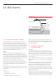
BOC Smootharc Advance II MIG 250C Operating manual 3.0 MMA Process Schematic of MMA process in operation )OX[ &RYHULQJ :HOG 0HWDO 6ODJ &RUH :LUH $UF :HOG 3RRO :RUNSLHFH 3.1 Introduction Arc welding, although in the past principally the tool of tradesmen and fabricators, has in recent years found increasing usage with small workshops, farmers, handyman-hobbyists amongst others.
BOC Smootharc Advance II MIG 250C Operating manual Having decided on a welding machine, appropriate accessories are required. These are items such as welding cables, clamps, electrode holder, chipping hammer, helmet, shaded and clear lenses, scull cap, gloves and other personal protective equipment. BOC stocks a huge range of personal protective equipment. This combined with BOC’s extensive network ensures fast reliable service throughout the South Pacific. 3.
BOC Smootharc Advance II MIG 250C Operating manual Electrodes and Typical Applications Name BOC Smootharc 13 BOC Smootharc 24 BOC Smootharc 18 BOC Smootharc S 308L BOC Smootharc S 316L BOC Smootharc S 309L AWS Class. E6013 Recommended Electrode Sizes Application A premium quality electrode for general structural and sheet metal work in all positions including vertical down using low carbon steels E7024 An iron powder electrode for high speed welding for H-V fillets and flat butt joints.
BOC Smootharc Advance II MIG 250C Operating manual 17 Generally Recommended Current Range for BOC Smootharc 13 Correct Travel Speed Size of Electrode (mm) 2.5 3.2 4.0 5.0 The electrode should be moved along in the direction of the joint being welded at a speed that will give the size of run required. At the same time the electrode is fed downwards to keep the correct arc length at all times. As a guide for general applications the table below gives recommended run lengths for the downhand position.
BOC Smootharc Advance II MIG 250C Operating manual Layers Butt Welding Electrode Angle for 1st and 2nd Layers Face Reinforcement Weld Beads Electrode Angle for Subsequent Layers Weld Face Layers Root Face Weld Beads Weld Beads Layers Root Gap Electrode Weld Pool Slag A Weld Metal Weld Beads Layers Direction Of Welding 3.6 Types of Joints Double ‘V’ Butt Weld Used on plate of 12 mm and over in thickness when welding can be applied from both sides.
BOC Smootharc Advance II MIG 250C Operating manual 19 Welding Progression Angle (OHFWURGH ² Ý :HOG 0HWDO 6ODJ $UF :HOG 3RRO :RUNSLHFH 'LUHFWLRQ RI :HOGLQJ General notes on Butt Welds The first run in a prepared butt weld should be deposited with an electrode not larger than 4.0 mm. The angle of the electrode for the various runs in a butt weld is shown. It is necessary to maintain the root gap by tacking at intervals or by other means, as it will tend to close during welding.
BOC Smootharc Advance II MIG 250C Operating manual Convex Fillet Weld Concave Fillet Weld Actual Throat & Effective Throat Actual Throat Effective Throat Actual Throat Convexity Actual Throat & Effective Throat Concavity Convexity Concavity Leg Leg Size Size Effective Throat Leg Lengh Leg Lengh Size Theoretical Throat Theoretical Throat Theoretical Throat Leg Size Leg Theoretical Throat The following terms and definitions are important in specifying and describing fillet welds.
BOC Smootharc Advance II MIG 250C Operating manual Recommended Electrode Angles for Fillet Welds 1st Run 21 Recommended Angles for Overhead Fillet Welds 2nd Run ee doedodde crotrrtor lcetlecct ElEeEEle 55–60° 55–60° 55–60° 55–60° 40° 40° 40° 40° 3rd Run Multi-run Fillet 15˚ 45˚ 30˚ 20–30° 20–30° 20–30° 20–30° 6 666 5 3 333 5 55 1 111 2 2224 444 Recommended Electrode Angles for Fillet Welds Multi-run horizontal fillets have each run made using the same run lengths (run length per electrode table)
BOC Smootharc Advance II MIG 250C Operating manual Slag Inclusions Undercutting This defect can be prevented by: →→ a uniform travel speed →→ a tighter weaving motion →→ complete slag removal before welding →→ using a smaller electrode →→ keeping the slag behind the arc which is done by shortening the arc, increasing the travel speed, or changing the electrode angle. Undercutting Undercutting is a groove melted in the base metal next to the toe or root of a weld that is not filled by the weld metal.
BOC Smootharc Advance II MIG 250C Operating manual 4.0 General Welding Information 4.1 Recommended Welding Parameters Argoshield® Light [Mild Steel Solid Wire] Indicative Welding Parameters Dip Transfer Material thickness (mm) 1–1.6 2 3 4 Wire diameter (mm) 0.8–0.9 0.8–0.9 0.8–0.9 0.9–1.0 Voltage (volts) 14–16 16–17 16–18 16–18 Wire feed speed (m/min) 3.5–5.0 4.0–7.0 4.0–7.0 4.0–7.
BOC Smootharc Advance II MIG 250C Operating manual Argon [Aluminium Solid Wire] Indicative Welding Parameters Solid Wire Material thickness (mm) 4.0 5.0 8.0 Welding position Horizontal Horizontal Horizontal Wire diameter (mm) 1.2 1.2 1.2 Current (amps) 160–180 210–220 215–225 Voltage (volts) 21–23 22–24 22.5–24.5 Wire feed speed (m/min) 8.0–9.0 10.0–10.6 10.2–10.
BOC Smootharc Advance II MIG 250C Operating manual 5.0 Correct Application Techniques Electrical stickout C S V A E Contact Tube Setback Standoff Distance Visible Stickout Arc length Electrical Stickout Gas Nozzle Contact Tube C Consumable S Electrode V E A Workpiece Correct Application Techniques Direction of welding. MIG welding with solid wires takes place normally with a push technique. The welding torch is tilted at an angle of 10° towards the direction of welding.
BOC Smootharc Advance II MIG 250C Operating manual Electrical stickout Short Short Travel speed Normal Normal Long Long Electrical stickout The electrical stickout is the distance between the end of the contact tip and the end of the wire. An increase in the electrical stickout results in an increase in the electrical resistance. The resultant increase in temperature has a positive influence in the melt-off rate of the wire that will have an influence on the weldbead profile.
BOC Smootharc Advance II MIG 250C Operating manual 6.0 Package Contents Package Contents Power source with input cable MIG Torch BOC Argon regulator Work return lead 1× gas hose with quick release ✓ Binzel MB 36KD ✓ ✓ ✓ Wire feed rollers Knurled 0.8-0.9/1.0-1.2 U Groove 0.8-0.9/1.0-1.2 V Groove 0.6-0.8/0.9-1.0/1.0-1.
BOC Smootharc Advance II MIG 250C Operating manual 7.0 Installation Installation for MIG/MAG process A Installation for MMA process 250C Smootharc Advance II B 2T 4T C A m/min D Smootharc Advance 2T 4T C A V B 0 10 INDUCTANCE WARNING 15A PLUG FITTED FOR DEMONSTRATION ONLY. Max 200A @ 20% duty cycle for 15A plug. For full output a 32A, 250V, 3-pin plug should be fitted by a certified electrician along with the additional input cable supplied. 7.
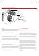
BOC Smootharc Advance II MIG 250C Operating manual 29 8.0 Operation Set-up Front of MIG 250C Inside of MIG 250C Wire Inch 7 Process selection switch (MMA, MIG) 1 Voltage 2 Wire feed speed and Arc current 3 Inductance 4 Positive dinse connector 5 Negative dinse connector 6 Pigtail 8.1 MIG Welding Set-up 8.
BOC Smootharc Advance II MIG 250C Operating manual 9.0 Control Panel Control Panel of MIG 250C Voltage meter Power indicator light 250C Smootharc Advance II 2T 4T 2T/4T button Process selection switch A Current meter/ Wire speed meter m/min V Inductance Knob 0 10 INDUCTANCE 0 10 CRATER ARC CURRENT 0 V 10 VOLTAGE Wire speed/Arc current knob Voltage Knob 9.1 Controls Wire speed/Arc current This is obtained by using the 2T/4T button on the machine front face.
BOC Smootharc Advance II MIG 250C Operating manual 9.2 31 Inductance Inductance is defined as the rise in current to above normal, in any electrical circuit that results in the melting of the wire at some point. Consider dip transfer (short ¬circuiting arc) in action. Before the wire strikes the work-piece, there is no flow of current and the OCV has maximum value. When the wire strikes the work-piece it creates what is known as a “dead short”.
BOC Smootharc Advance II MIG 250C Operating manual 10.
BOC Smootharc Advance II MIG 250C Operating manual 11.0 Replacement Parts MIG 250C Suitability Description Part No. Torch ✓ Binzel MB Grip 36KD Air Cooled 3m 014.0234 Wire Feed Rollers ✓ Self-Shielded Flux Cored ✓ ✓ Aluminium ✓ ✓ ✓ ✓ Steel, Stainless Steel Knurled 0.8–0.9 ADVANCEKNROL0809 Knurled 1.0–1.2 ADVANCEKNROL1012 Knurled 1.2–1.6 ADVANCEKNROL1216 U Groove 0.8–0.9 ADVANCEUROL0809 U Groove 1.0–1.2 ADVANCEUROL1012 U Groove 1.2–1.6 ADVANCEUROL1216 V Groove 0.6–0.
BOC Smootharc Advance II MIG 250C Operating manual 12.0 Periodic Maintenance The working environment or amount of use the machine receives should be taken into consideration when planning maintenance frequency of your MIG 250C welder. Preventative maintenance will ensure trouble-free welding and increase the life of the machine and its consumables. 12.1 Power Source • Check electrical connections of unit at least twice a year. • Clean oxidised connections and tighten.
BOC Smootharc Advance II MIG 250C Operating manual 13.0 Technical Specifications Specifications Part No. Power voltage Frequency Rated input current (Ieff) Output current Output Voltage Duty cycle 30 % 35 % 60 % Power factor Efficiency Wire speed Wire spool diameter Wire diameter Housing shielding grade Insulation grade Suitable thickness Dimensions L × W × H Weight approx. Wire feeder Standards MIG/MAG MMA ADVANCE II 250C Single phase 240 V ±15 % 50/60 Hz 32A 50 A to 250 A 50 A to 220 A 16.5 V to 26.
BOC Smootharc Advance II MIG 250C Operating manual 14.0 Warranty Information 14.1 Terms of Warranty 14.3 Warranty Period The Smootharc ADVANCE II machine has a limited warranty that covers manufacturing and material defects only. The warranty is affected on the day of purchase and does not cover any freight, packaging and insurance costs. Verbal promises that do not comply with terms of warranty are not binding on warrantor.
BOC Smootharc Advance II MIG 250C Operating manual 37
BOC Smootharc Advance II MIG 250C Operating manual
For more information contact the BOC Customer Service Centre. BOC Australia 131 262 www.boc.com.au BOC Limited ABN 95 000 029 729 10 Julius Avenue, North Ryde NSW 2113, Australia BOC Limited WN007748 970–988 Great South Road, Penrose, Auckland, New Zealand © BOC Limited 2015. BOC is a trading name of BOC Limited, a Member of The Linde Group. Reproduction without permission is strictly prohibited. Details given in this document are believed to be correct at the time of printing.