
Installation Sheet
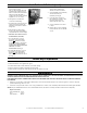

Fig. 5
Fig. 6
Form No. 3725-69 (Revised 2/24/17) © 2017 Bobrick Washroom Equipment, Inc.
3
6. Mount unit into wall opening with
shims between framing and
cabinet at screw hole locations.
7. Secure using #8x1-1/4'' (4.2 x 32mm)
sheet metal screws (not
furnished). (See Fig. 6)
8. Insert absorbent ceramic into
place. Make sure ceramic is fully
inserted so that it does not
interfere with the dryer cover.
9. Connect activation sensor wires
to dryer.
10. Replace dryer cover by engaging
the top side fi rst, then secure with
screws.
1. Turn electrical power supply on.
2. Wait until activation sensor light fl ashes green.
3. Position hands under air outlet, within (4") of air outlet opening.
4. Dryer should turn on. Warm air should blow from air outlet.
5. Remove hands from under air outlet and dryer should stop (within 2 seconds).
WARNING: MOTOR LAMINATIONS ARE LIVE. TURN ELECTRICAL POWER SUPPLY OFF BEFORE DOING ANY MAINTENANCE OR SERVICE
TO DRYER. DRYER MUST NOT BE OPERATED UNLESS COVER IS IN PLACE.
FOR PROPER ELECTRICAL CONNECTIONS, CHECK LOCAL BUILDING CODE. UNIT MUST BE INSTALLED BY A QUALIFIED LICENSED
ELECTRICIAN
1. Exterior of cover should be cleaned with a damp cloth to remove dust and surface dirt. Do not use abrasive agents or solvents as they may
permanently damage surface of cover.
2. At least once every 6 months remove cover. Using a small brush or vacuum, clean out buildup of dust and lint from air-intake grille and baffl e.
NOTE: if dryer is installed where there is a lot of dust and dirt in the air, the interior of the dryer should be cleaned out more frequently
Replacement Parts:
Absorbent Material 3725-23
Door 3725-53
Motor Brushes 700-121.
a. Electrical supply entry holes are
located in the rear and
sides of cabinet. Supply cable with
supplementary insulation into one
of these locations in the unit cabinet.
Cabinet should be fi tted with a
conduit connection. Plastic grommet
supplied to use as necessary.
b. This appliance is intended for
connection to fi xed wiring.
c. A fused means for disconnection in
all poles must be provided in the
fi xed wiring in accordance with the
wiring rules.
d. Check that the electrical rating
shown on the dryer (rating label) is
compatible with the electrical supply.
e. WARNING: THIS PRODUCT MUST
BE GROUNDED (EARTHED).
f. For 115–Volt Dryers, connect
ground wire to ground terminal
marked
, the black or hot wire
to terminal marked L1, and neutral
or white wire to terminal marked N.
A DEDICATED LINE IS REQUIRED
FOR EACH 115-VOLT
INSTALLATION. (See Fig. 5)
g. For 208–240 Volt Dryers, connect
ground wire to ground terminal
marked
and the 208–240 volt
wires to terminal marked L1 and L2.
(See Fig. 5)
Check Dryer Operation
Maintenance
Installation of Cabinet (cont.)