Instruction Manual Model 970 Portable Radiation Spectrum Analyzer Berkeley Nucleonics Corporation 2955 Kerner Blvd., San Rafael, CA 94901 Phone: 415-453-9955, Fax: 415-453-9956, Email: info@berkeleynucleonics.com, Web: www.berkeleynucleonics.
Firmware Release Software Release 2.1.3 Manual Version 1.0 © 2013 All rights reserved. Printed in U.S.A. WARRANTY Berkeley Nucleonics Corporation warrants all instruments, including component parts, to be free from defects in material and workmanship, under normal use and service for a period of one year. If repairs are required during the warranty period, contact the factory for component replacement or shipping instructions. Include the serial number of the instrument.
Table of Contents Table of Contents ..............................................................................................................................i 1 Introduction ................................................................................................................ 1 1.1 Model 970 System Requirements.............................................................................. 1 1.1.1 Model 970 Technical Specification ................................................................
Introduction Thank you for purchasing a Model 970 Portable Multi-Channel Analyzer (MCA). A lot of time and effort was spent trying to make the Model 970 hardware, software, and this manual, as userfriendly and error-free as possible, but we cannot guarantee that no mistakes or omissions are present. All software (and manuals, for that matter) are “works-in-progress,” and will be updated from time to time. These updates will be posted on our website, http://www.berkeleynucleonics.
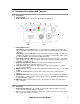
1.2 Hardware Description and Controls 1.2.1 Front Panel 1. On/Off Switch. 2. Power On LED. Glows red when the Model 970 is powered on. 3. Charge Mode Switch. Slow Charge: Internal NiMH batteries are recharged using a trickle current which will fully charge depleted batteries in about 14 hours and safely maintain them at full capacity indefinitely. Fast Charge: Internal NiMH batteries are undergoing a fast charge. Batteries will be fully charged in about three to four hours.
1.2.3 Battery Compartment 1. Battery Type Selection Switch. Recharge position: Allows NiMH batteries to be charged. Standard position: The battery charging circuitry is disabled so that non-rechargeable alkaline batteries can be kept in the Model 970 while it is connected to external power 1.3 Powering the Model 970 1.3.1 AC Power Supply A 110VAC or 220VAC to 12VDC power supply is provided with the Model 970.
1.3.3 Using Alkaline Batteries It is not a problem using non-rechargeable batteries in the Model 970. Remove the four screws on the Rear Panel and replace the NiMH batteries with AA alkaline batteries. However, you must be absolutely sure to switch the Battery Type Selection Switch to the Standard position to bypass the 970’s internal charging circuitry. Failure to do this may result in catastrophic damage to the Model 970. Switch back to the Recharge position when NiMH batteries are reinstalled. 1.3.
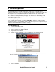
2 General Operation The Model 970 hardware and SNAP-MCA software are designed to connect the 970 to a computer as painlessly as possible. The 970 must be connected to a serial port via a serial cable. The computer must be using Windows 98, Windows 98 SE, Windows ME, Windows 2000, Windows XP, or Windows 7. The COM port must utilize a 16550 (or higher) high-speed UART; this is standard on virtually all Pentium (and higher) class motherboards.
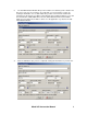
8. The Add New Detector window will open and contain some default “generic” data the first time it is used. If you are in a hurry to try out the 970, you can accept these values by clicking the Add button. It is recommended, that you take a few moments and fill in the information for the detector you will be using. All fields must contain information. If you click the Cancel button, SNAP-MCA will revert to the Select Detector window, which will be blank.
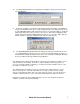
. The Select Detector window is now displayed, showing the detector just entered. Click Use This Detector. 11. A window showing the serial number of the Model 970 and the number of the COM port being used is displayed. Click Yes to enable the High Voltage to the displayed value or No to start SNAP-MCA with the High Voltage turned off.
3 Functions, Controls, and Displays 3.1 SNAP-MCA Main Window This window is the starting point for all Model 970 functions. This section describes in general terms the controls and displays on the main window. Virtually all functions can be performed using either the mouse or combinations of keystrokes. 3.2 Menu Bar Essentially all SNAP-MCA functions can be accessed through the Menu Bar, including those triggered by buttons on the SNAP-MCA Main Window.
The next two menu items, Capture Screen to Clipboard and Save Spectrum as Graphic, relate to the graphical representation of the spectrum, referred to in this document as the Chart. These allow the Chart to be copied to the Clipboard (and subsequently pasted into a word processing or graphics program) or saved as a graphics file. These relate only to the Chart exactly as displayed, and do not carry over any other portion of the window.
These items are identical in function to the four buttons along the top of the Acquisition Controls and Indicators portion of the screen. Note: No warnings are given if the current spectrum has not been saved! Detector Status displays a small window displaying current information about the detector being used, loaded ROI and library files, as well as the state of Energy and Efficiency Calibrations.
Select/Change automatically disables the 970’s HV supply to allow for safe changing of detectors. A new detector is selected from the list in a manner similar to that performed during SNAP-MCA startup. Once a new detector has been selected, that detector’s settings (Hardware Settings, Energy and Efficiency Calibrations, and the last-used ROI with that detector) are loaded, and the HV is enabled.
except for Full Screen, which closes any displayed panel and restores the Spectrum Display to the largest possible size. The functions contained in these panels are discussed in detail in the Button Panel section. Multi Channel Scaling Mode disables and hides the SNAP-MCA Main Window, and opens a new window for performing multi-channel scaling. This function is discussed in detail in Section 5 of this Manual.
Misc Menu This menu item is for special functions that do not easily fit into other categories. All of these items have been suggested or requested by users. Collect Multiple Sequential Spectra opens a window where the Model 970 can be told to collect a fixed number of spectra (or to sample continuously). At the end of each Acquisition, the spectrum file is saved with a sequential file name. Alternatively (or, additionally), a brief ROI report can be saved.
When Show Background Subtracted is checked, the loaded Background Spectrum is visually removed from the Live Spectrum. It does not affect display of a Live Spectrum. Regardless of this visual setting, if a Background has been loaded, it is subtracted in all analysis functions. This menu item will be unavailable if no Background Spectrum has been loaded.
Sound Menu Three options exist for audible notification to the user that the acquiring of a spectrum has been completed. First is No Sound, i.e. the Acquisition just stops. In the second, Ring Once on Acquisition End, a single notification sound (the Windows “default” sound, usually a “ding”) is made upon completion of an Acquisition.
The 970 Support Website is a hyperlink to (you guessed it!) the 970 Support Website. The About function opens a window containing information about SNAP-MCA software and the Model 970 hardware. Version Information simply displays the version number of the SNAP-MCA software. 3.3 Button Bar The left two buttons (Fine and MCS) on this portion of the SNAP-MCA Main Window provide quick access to the Energy Calibration window and the Multi Channel Scaling mode. These functions are discussed in Section 6.
The Show button will only be enabled if an Energy Calibration has been performed. Clicking the Show button displays marker lines at the energies where enabled library peaks for the current isotope should reside. When the marker lines are displayed, the button caption becomes Hide. If Yield is also selected, the heights of these lines are proportional to the yield for each energy. If an Efficiency Calibration has been performed, Eff x may be selected.
3.5 New User Hints Bar If Show New User Hints has been enabled in the View menu on the Menu Bar, a sentence or two appears here that briefly describes the function for any display or control the mouse cursor is currently over. 3.6 Spectrum Display This area graphically displays the spectrum data collected. This area can be zoomed by using and clicking the mouse and “dragging a box” around the area of interest, from upper-left to lowerright.
The first group of three boxes (towards the left) reflect data for the individual channel over which the mouse cursor is located. These are the channel number, the energy associated with that channel (only if an Energy Calibration has been performed), and the number of counts in that particular channel. If a Background Spectrum has been loaded, the count displayed will reflect the Background-subtracted counts if Show Background Subtracted has been selected under the View menu on the Menu Bar.
Spectrum Clear (red background). Indicates that the Spectrum Display contains no data, and the 970 is not acquiring data. Acquiring (light green background). Indicates that a spectrum is currently accumulating. Acquisition Stopped (yellow background). Indicates that the 970 is not currently acquiring data, but the Spectrum Display contains data. Spectrum Loaded (yellow background).
3.10 Button Panel The Button Panel provides access to the primary “workhorse” functions of SNAP-MCA. Each of these is described fully below. Full Screen This hides all panels and makes the Spectrum Display as large as possible within the confines of the window borders. Hardware This displays the Hardware Panel for adjusting the 970 hardware controls. To adjust other Hardware Settings, the Allow Edit checkbox must be checked.
If Ramp HV is not checked, the High Voltage will change as instantaneously as possible. This is usually fine for most detectors. If needed, Ramp HV can be checked and the detector supply voltage will always be changed at the rate displayed. This can range from 6 to 219 seconds per 100 volts. The detector Input and Polarity can be selected from the dropdown menu. INPUT1 is the series “C” connector where signal and detector supply voltage are carried on the same line.
Current ROI Set Name: displays the filename of the currently loaded ROI Set. If no file is displayed, then no ROI Set is currently loaded. Note: A small display will appear below Current ROI Set Name: (not shown in the display above) that flags the fact that the current ROI Set has been altered but not yet been saved. The small panel (Drag cursor to) immediately below this normally has Zoom (normal) checked.
Efficiency This displays the Efficiency Calibration Panel. This Efficiency Calibration is based on an ROI Set, but the same calibration is also used when performing peak-based or library-based spectrum analyses. An ROI Set, therefore, must be created and/or loaded before this panel is available. Efficiency Calibrations are unique to specific 970/ROI file/Detector combinations. Current ROI Set Name: displays the filename of the currently loaded ROI Set.
The Cancel button will make any alterations made on the Efficiency Calibration Panel revert back to the ones used in the most recent Efficiency Calibration. Every time an Efficiency Calibration is performed, a report is generated and stored in the 970 Cal Files directory. This report can be viewed, printed, or saved by clicking the Report… button. Note: The contents of the report and use of the report window are discussed in detail in other portions of this manual.
If the Allow Edit box is selected, the controls for editing the found peaks are enabled. When Double Click Adds Peak is selected, double clicking on a portion of the spectrum will add a “found peak.” This new peak is treated the same as the others found by the computerized search, and this method of adding “found peaks” may be used instead of, or as a supplement to, the computerized search.
Sample Info This displays the Sample Data Panel for entering sample descriptions and quantities. The Sample Description input box allows the entry of a brief description or note. This will be displayed in all subsequent analyses and generated reports, and saved with the spectrum file. If Use Sample Quantity is checked, two controls will be enabled that allow entry of a sample quantity and the associated units. These values will be saved with the spectrum, and used and displayed in subsequent analyses.
The “Print Preview” or “Report” Screen This screen is used to display, save, and print all reports generated by SNAP-MCA. The Print button will send the report to any printer via the Windows operating system. The report should print exactly as displayed. The Save button allows the report to be saved as either a rich text file (rtf) or a plain text file (txt). Both formats can be used with most word processors; saving as an .rtf keeps the look of the file exactly as it is displayed (i.e.
4 Using the Library Editor Two libraries are distributed with SNAP-MCA and SNAP-MCA Full. As a general rule, SNAPMCA is intended for NaI (Tl) detectors, and SNAP-MCA Full is intended for detectors with higher resolution. Both were created from the same information, contained in “Radioactive Decay Data Tables” by David C. Kocher, Report DOE/TIC-11026. The data was originally formatted for computer by Grove Engineering from information provided by RSIC.
Use the Save Lib. button to save the library as it exists, reflecting any changes that have been made. This can also be used to save the Library under a different name. The Cancel button can be used to close the Library Editor without saving any changes that have been made since the previous save. If no changes have been made since the previous save, the button will read Close. Check Allow Edit of Nuclide Name and Half Life to allow editing of those values, if needed.
Pri. This column of radio buttons is used to indicate which energy is designated as the “primary peak” for the isotope. The primary peak MUST be present in a spectrum (in addition to the secondary peak) in order to positively identify the isotope and activity will be calculated based in the primary peak. Therefore, the energy with the highest yield is usually designated as the primary peak. It is acceptable to designate the same energy as both the primary and secondary peaks, but the energy must be enabled.
5 Using MCS Mode The Multi Channel Scaling mode is used for the application of watching or recording changes in count rate over time. An analog meter-style display also shows the current count rate. MCS mode allows you complete control over how the data is accumulated and displayed. 5.1 Menu Bar File Menu The first menu item, Save Chart as csv… saves all the data collected in the current Acquisition to a comma separated value (csv) file.
Utility Menu The first four menu items Start (or Restart) Acquisition, Stop Acquisition, Clear Spectrum, and Clear Spectrum and Start New Acquisition are self-explanatory, and their functions are identical to the four buttons near the upper right of the Chart display. View Menu Show New User Hints enables/disables the New User Hints Bar, which displays a sentence or two briefly describing the function for any display or control the mouse cursor is currently over. Disabling (i.e.
Immediately below the four buttons is a status display showing the current status of data acquisition. Moving downward, the next object is the white Time (sec) input box, with a checkbox immediately to its left. If the checkbox is checked, the 970 will stop acquiring a spectrum when the total counting time equals this value. Time units are in seconds. An Acquisition cannot be started or continued if the checkbox is checked and the Acquisition time equals or exceeds the amount of time in the input box.
5.3 MCS Analog Panel This panel displays an analog-style meter movement of the current Acquisition. The settings for this panel can be altered independently of the Chart display. If Alarm at: is checked, the analog display will turn red and an audible alarm will sound, if the count rate exceeds the value contained in the input box. The alarm will reset when the count rate falls below the alarm level, or when the box is unchecked.
6 Procedures 6.1 Calibrating a Detector with Model 970 In order to use the Model 970 with a given detector, the following must be done (in this order): 1. Adjust Hardware Settings. 2. Perform Energy Calibration. 3. Perform a Shape Calibration. Following this step, the 970 is ready to provide Qualitative Analysis. 4. Create a “Regions of Interest” (ROI) Set. This is in preparation for Efficiency Calibration, which must be coupled to an ROI Set. 5. Perform Efficiency Calibration.
6.2.2 Input and Polarity The 970 has two detector inputs. INPUT 1 is the series “C” connector right next to the DB9 serial connector. This input has the signal and the High Voltage coupled just as on most hand-held instruments. If your detector has only one connector, INPUT 1 is the one you should use. If your detector has two connectors, one for High Voltage and one for the signal, you should use INPUT 2. The SHV connector carries the High Voltage for INPUT 2 and the BNC connector accepts INPUT 2’s signal.
It is worth mentioning that the Gain settings are arbitrary and not absolute. In other words, if you put in a pulse of exactly 1000 mV with an overall Gain of x1, the pulse will not necessarily appear in channel 1000. Similarly, a positive pulse of exactly 1000 mV will not necessarily appear in the same channel of a negative but otherwise identical pulse. This is normal and is only mentioned here so no surprise is experienced if you put a pulse generator on the 970.
Procedure 1. Click on the Hardware button on the 970 Button Panel. This will open the Hardware Settings Panel along the bottom of the Spectrum Display. 2. Check the Allow Edit check box to enable the Hardware Settings. 3. Ensure that the HV is set to a reasonable value. For relatively new 970 users, Coarse Gain should be at x2 (the lowest setting) and the Fine Gain should be at x0.500 for an overall Gain of x1; the Threshold should be at 50 mV. 4.
Discussion SNAP-MCA uses a linear interpolation between Energy Calibration points. More sophisticated modeling was not implemented because the wide range of characteristics in the detectors supported by the 970 makes it impossible to accurately model for all possible energy response. It was also determined that there were certain advantages to using this method, especially in the low-energy range. In short, the more data points entered, the more accurate the Energy Calibration will be.
137 3. Assuming a Cs spectrum is displayed, assign channels to the energies by: 4. Clicking the radio button next to “32.89” keV. The keV box and the channel box to its immediate right will turn yellow. 5. Move the mouse cursor over the 32.89 keV peak on the Spectrum Display and double click. A yellow line will appear on the spectrum indicating the location of this Energy Calibration point, and the channel number will appear in the channel box. 6.
6.4 Perform a Shape Calibration Prerequisites This procedure assumes that the detector is attached to the Model 970, the 970 is switched on, SNAP-MCA software has been successfully started, a radioactive source of known isotopic composition is on the detector, the 970 Hardware Settings have been set appropriately, and an Energy Calibration has been performed.
6.5 Create a Regions of Interest (ROI) Set Prerequisites This procedure assumes that the detector is attached to the Model 970, the 970 is switched on, SNAP-MCA software has been successfully started, a radioactive source of known isotopic composition is on the detector, the 970 Hardware Settings have been set appropriately, and an Energy Calibration has been performed. Discussion An ROI Set must be created in order to perform a detector Efficiency Calibration.
3. From the Peak-Based Panel, click on Find Peaks. The peaks and their ROIs will be highlighted automatically in green. 4. The found peaks can now be edited, if desired, by clicking on the Allow Edit box. The user can now adjust the centroid and the left and right edges of each peak region. Peaks can also be added as well as deleted. 5. To add a peak, simply click on the Double Click Adds Peak box. Locate a peak on the spectrum with the mouse and double click. Another peak region will appear. 6.
11. Type a name in the Save ROI Set dialog, and click the Save button. 12. Once the set has been saved, the panel along the bottom of the Spectrum Display will switch over to the ROI Panel to allow additional editing, if desired. 13. Editing the ROI Set from the ROI Panel is described in the next section. Procedure: Manually Creating or Editing an ROI Set (“Manual Method”) 1. Acquire a spectrum with known peaks. It is usually a good idea to start with a relatively 137 simple spectrum such as Cs.
2. Click on ROI Panel on the SNAP-MCA Button Panel. This will open the ROI Edit Settings Panel along the bottom of the Spectrum Display. 3. To create a new ROI Set, click on the New ROI Set button to assign a file name to the new set. (If this is not done before the following steps, a “Not Saved!” warning will be displayed as a reminder. This warning will also be shown any time the ROI as displayed is different from the saved ROI file.) 4. To create an ROI by dragging on the Spectrum Display: 5.
Discussion Efficiency Calibrations are attached to specific ROI Sets. Known activities of known isotopes are assigned to specific energies in the spectrum. SNAP-MCA uses a linear interpolation between Efficiency Calibration points to allow Quantification of isotopes for which no specific calibration source is available. The same Efficiency Calibration is used when performing ROI, peak, or library-based Quantification.
5. 6. 7. 8. 9. 10. 11. 12. 13. 14. 15. If the ROI is one contained in the calibration source: Select the nuclide for the ROI from the Associated Nuclide drop-down list. Select the peak energy for the ROI from the Associated Peak drop-down list. Enter the activity of the source being used in the Activity box. Select the appropriate units from the Units drop-down list.
7 Support Programs Several levels of technical support are available for users of the Model 970. 7.1 Factory Technical Support Berkeley Nucleonics offers fast and efficient support from our headquarters in California, as well as several satellite offices domestically and abroad. Visit our website at http://www.berkeleynucleonics.com/ for the support and service center nearest you, or call 800234-7858.
8 Specifications Preamplifier Type: Input: Output: Charge Sensitive Negative Current (anode) Positive HV supply variable 0 V to 2000 V (0.5 mA) Negative HV supply also available Type: Speed: 4096 channel, 14-bit pipelined 50 MHz ADC Pulse Processing Type: Shaping: Gain: LLD: ULD: Zero: Digital, Trapezoidal Shaping 250 ns to 10 µs Digital, x1, x2, x4, x15, x35, x125, and x250. 0 to 100 % of full scale digitally adjustable in .006 % intervals 0 to 100 % of full scale digitally adjustable in .