
Service manual


3
),(
)]/1([
1
)/1(
)( ∞→
+
×
+
= n
RCs
RCs
s
sG
n
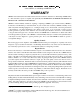
Fig. 3. Pulse Shapes for Good Signal-to-Noise Ratios.
Total preamplifier-amplifier pole-zero cancellation
requires that the preamplifier output pulse decay
time be a single exponential decay and be matched
to the pole-zero cancellation network. The variable
pole-zero cancellation network allows accurate
cancellation for all preamplifiers having 30-
s or
greater decay times. Improper matching of the pole-
zero network will degrade the overload performance
and cause excessive pileup distortion at medium
counting rates. Improper matching causes either an
undercompensation (undershoot is not eliminated)
or an overcompensation (output after the main
pulse does not return to the baseline but decays to
the baseline with the preamplifier time constant).
The pole-zero adjust is accessible on the front
panel of the 575A and can easily be adjusted by
observing the baseline on an oscilloscope with a
monoenergetic source or pulser having the same
decay time as the preamplifier under overload
conditions. The adjustment should be made so that
the pulse returns to the baseline in the minimum
time with no undershoot.
1.3. ACTIVE FILTER
When only FET gate current and drain thermal
noise are considered, the best signal-to-noise ratio
occurs when the two noise contributions are equal
for a given input pulse shape. The Gaussian pulse
shape (Fig. 3) for this condition requires an
amplifier with a single RC differentiation and n
equal RC integrations where n approaches infinity.
The Laplace transform of this transfer function is
where the first factor is the single differentiation,
and the second factor is the n integrations. The
active filter approximates this transfer function.
Figure 3 illustrates the results of pulse shaping in an
amplifier. Of the four pulse shapes shown the cusp
would produce minimum noise, but this is
impractical to achieve with normal electronic
circuitry and would be difficult to measure with an
ADC. The true Gaussian shape deteriorates the
signal-to-noise ratio by only about 12% from that of
the cusp and produces a signal that is easy to
measure but requires many sections of integration
(n
). With two sections of integration the
waveform identified as a Gaussian approximation
can be obtained, and this deteriorates the signal-to-
noise ratio by about 22%. The ORTEC active filter
network in the 575A provides a fourth waveform in
Fig. 3; this waveform has characteristics superior to
the n = 2 Gaussian approximation, yet obtains them
with two complex poles and a real pole. By this
method, the output pulse shape has a good signal-
to-noise ratio, is easy to measure, and yet requires
only a practical amount of electronic circuitry to
achieve the desired results.