
Service manual


16
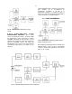
LINEARITY The integral nonlinearity of the 575A
can be measured by the technique shown in
Fig. 21. In effect, the negative pulser output is
subtracted from the positive amplifier output to
cause a null point that can be measured with
excellent sensitivity. The pulser output must be
varied between 0 to 10 V, which usually requires an
external control source for the pulser. The amplifier
gain and the pulser attenuator must be adjusted to
measure 0 V at the null point when the pulser
output is 10 V. The variation in the null point as the
pulser is reduced gradually from 10 V to 0 V is a
measure of the nonlinearity. Since the subtraction
network also acts as a voltage divider, this variation
must be less than
(10 V full scale) × (±0.05% maximum nonlinearity)
×(1/2 for divider network)
=±2.5 mV for the maximum null-point variation.
OUTPUT LOADING Use the test setup of Fig. 21.
Adjust the amplifier output to 10 V and observe the
null point when the front panel output is terminated
in 100
. The change should be <2.5 mV.
NOISE Measure the noise at the amplifier unipolar
output with maximum amplifier gain and 3-
s
shaping time. Using a true-rms voltmeter, the noise
should be <5
V × 750 (gain), or 3.75 mV.
For an average responding voltmeter, the noise
reading would have to be multiplied by 1.13 to
calculate the rms noise. The input must be
terminated in 100
during the noise
measurements.
5.3. SUGGESTIONS FOR
TROUBLESHOOTING
In situations where the 575A is suspected of a
malfunction, it is essential to verify such
malfunction in terms of simple pulse generator
impulses at the input. The unit must be
disconnected from its position in any system, and
routine diagnostic analysis performed with a test
pulse generator and oscilloscope. It is imperative
that the testing not be performed with a source and
detector until the amplifier performs satisfactorily
with the test pulse generator.
The testing instructions in Section 5.2 should
provide assistance in locating the region of trouble
and repairing the malfunction. The two side plates
can be completely removed from the module to
enable oscilloscope and voltmeter observations.
5.4. FACTORY REPAIR
This instrument can be returned to the ORTEC
factory for service and repair at a nominal cost. Our
standard procedure for repair ensures the same
quality control and checkout as for a new
instrument. Always contact Customer Services at
ORTEC, (865) 483-2231, before sending in an
instrument for repair to obtain shipping instructions.
A Return Authorization Number is required and will
be assigned to the unit. This number should be
marked on the address label and on the package to
ensure prompt attention when the unit reaches the
factory.
5.5. TABULATED TEST POINT VOLTAGES
The voltages given in Table 5.1 are intended to
indicate typical dc levels that can be measured on
the PWB. In some cases the circuit will perform
satisfactorily even though, due to component
tolerances, there may be some voltage
measurements which differ slightly from the listed
values. The tabulated values should not be
interpreted as absolute voltages but rather should
be used as an aid during troubleshooting.
Table 5.1. Typical dc Voltages
Note: All voltages measured with no input signal,
with the input terminated in 100
, and all
controls set fully clockwise at maximum.
Location Voltage
T1 ±50 mV
T2 ±60 mV
T3 ±0.7 V
T4 ±1.0 V
T5 ±60 mV
T6 0 to
0.8 V
T7 ±6 mV