
Service manual


15
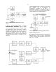
Fig. 21. Circuit Used to Measure Nonlinearity.
5. MAINTENANCE
5.1. TEST EQUIPMENT REQUIRED
The following test equipment should be used to
adequately test the specifications of the 575A
amplifier:
1. ORTEC 419 Precision Pulse Generator or 448
Research Pulser.
2. Tektronix 547 Series Oscilloscope with a type
1A1 plug-in or equivalent.
3. Hewlett-Packard 3400A rms voltmeter.
5.2. PULSER TEST*
FUNCTIONAL CHECKS Set the 575A controls as
follows:
Coarse Gain 100
Gain 7.5
Input Polarity Neg
Shaping Time Constant 1.5
s
a. Connect a positive pulser output to the 575A
input and adjust the pulser to obtain +10V at the
unipolar output. This should require an input
pulse of 13.3 mV using a 100-
terminator at
the input. Adjust PZ if necessary.
b. Change the input polarity switch to Pos and
then back to Neg while monitoring the output for
a polarity inversion.
c. Monitor the bipolar output for dc level of
<±5 mV; pulse shape should be bipolar. Return
to UNI.
d. Recheck the output pulse amplitude and adjust
if necessary to set it at +10 V with maximum
gain. Decrease the Coarse Gain switch stepwise
from 100 to 2 and ensure that the output
amplitude changes by the appropriate amount
for each step. Return the Coarse Gain switch to
100.
e. Decrease the Gain control from 7.5 to 2.5 and
check to see that the output amplitude
decreases by a factor of 2. Return the Gain
control to maximum at 7.5.
f. With the shaping jumpers set for 1.5
s
measure the time to the peak on the unipolar
output pulse; this should be 3.3
s (or 2.2 ).
*See IEEE Standards No. 301-1976.
Measure the time to baseline crossover of the
bipolar output; this should be 5.0
s (or 3.3 ).
g. Change the shaping jumpers to 0.5 and 3
s in
turn. At each setting, check to see that the time
to the unipolar peak is 2.2
. Return the jumpers
to 1.5
s.
OVERLOAD TESTS Start with maximum gain,
= 1.5 s, and a +10 V output amplitude. Increase
the pulser output amplitude by ×200 and observe
that the unipolar output returns to within 200 mV of
the baseline within 24
s after the application of a
single pulse from the pulser. It will probably be
necessary to vary the PZ ADJ control on the front
panel in order to cancel the pulser pole and
minimize the time required for return to the
baseline.