
Service manual


12
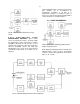
Fig. 14. System for High-Resolution Alpha-Particle
Spectroscopy.
Fig. 15. System for High-Resolution Gamma
Spectroscopy.
4.7. OPERATION IN SPECTROSCOPY
SYSTEMS
HIGH-RESOLUTION ALPHA-PARTICLE
SPECTROSCOPY SYSTEM The block diagram of
a high-resolution spectroscopy system for
measuring natural alpha particle radiation is shown
in Fig. 14. Since natural alpha radiation occurs only
above several MeV, an ORTEC 444 Biased
Amplifier is used to suppress the unused portion of
the spectrum; the same result can be obtained by
using digital suppression on the MCA in many
cases. Alpha-particle resolution is obtained in the
following manner:
a. Use appropriate amplifier gain and minimum
biased amplifier gain and bias level.
Accumulate the alpha peak in the MCA.
b. Slowly increase the bias level and biased
amplifier gain until the alpha peak is spread
over 5 to 10 channels and the minimum- to
maximum-energy range desired corresponds to
the first and last channels of the MCA.
c. Calibrate the analyzer in keV per channel using
the pulser and the known energy of the alpha
peak (see “Calibration of Test Pulser”) or two
known-energy alpha peaks.
d. Calculate the resolution by measuring the
number of channels at the FWHM level in the
peak and converting this to keV.
HIGH-RESOLUTION GAMMA SPECTROSCOPY
SYSTEM A high-resolution gamma spectroscopy
system block diagram is shown in Fig. 15. Although
a biased amplifier is not shown (an analyzer with
more channels being preferred), it can be used if
the only analyzer available has fewer channels and
only higher energies are of interest.
When a germanium detector that is cooled by a
liquid nitrogen cryostat is used, it is possible to
obtain resolutions from about 1 keV FWHM up
(depending on the energy of the incident radiation
and the size and quality of the detector).
Reasonable care is required to obtain such results.
Some guidelines for obtaining optimum resolution
are:
a. Keep interconnection capacitance between the
detector and preamplifier to an absolute
minimum (no long cables).
b. Keep humidity low near the detector-
preamplifier junction.
c. Operate the amplifier with the shaping time that
provides the best signal-to-noise ratio.
d. Operate at the highest allowable detector bias
to keep the input capacitance low.
SCINTILLATION-COUNTER GAMMA
SPECTROSCOPY SYSTEMS The ORTEC 575A
can be used in scintillation-counter spectroscopy
systems as shown in Fig. 16. The amplifier shaping
time constants should be selected in the region of
0.5 to 1.5
s for Nal or plastic scintillators. For
scintillators having longer decay times, longer time
constants should be selected.