
Service manual


11
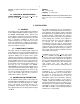
Fig. 11. System for Measuring Resolution with a Pulse
Height Analyzer.
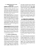
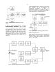
Fig. 12. System for Detector Current and Voltage
Measurements.
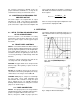
Fig. 13. Silicon Detector Back Current vs Bias Voltage.
The electronic noise-resolution spread can be
measured directly with a pulse height analyzer and
the mercury pulser as follows:
a. Select the energy of interest with an ORTEC
419 Precision Pulse Generator. Set the amplifier
and biased amplifier gain and bias level controls
so that the energy is in a convenient channel of
the analyzer.
b. Calibrate the analyzer in keV per channel, using
the pulser; full scale on the pulser dial is 10
MeV when calibrated as described above.
c. Obtain the amplifier noise-resolution spread by
measuring the FWHM of the pulser peak in the
spectrum.
The detector noise-resolution spread for a given
detector bias can be determined in the same
manner by connecting a detector to the preamplifier
input. The amplifier noise-resolution spread must be
subtracted as described in “Detector Noise-
Resolution Measurements.” The detector noise will
vary with detector size and bias conditions and
possibly with ambient conditions.
CURRENT VOLTAGE MEASUREMENTS FOR Si
AND Ge DETECTORS The amplifier system is not
directly involved in semiconductor detector current
voltage measurements, but the amplifier serves to
permit noise monitoring during the setup. The
detector noise measurement is a more sensitive
method than a current measurement of determining
the maximum detector voltage that should be used
because the noise increases more rapidly than the
reverse current at the onset of detector breakdown.
Make this measurement in the absence of a source.
Figure 12 shows the setup required for current
voltage measurements. An ORTEC 428 Bias
Supply is used as the voltage source. Bias voltage
should be applied slowly and reduced when noise
increases rapidly as a function of applied bias.
Figure 13 shows several typical current voltage
curves for ORTEC silicon surface-barrier detectors.
When it is possible to float the microammeter at the
detector bias voltage, the method of detector
current measurement shown by the dashed lines in
Fig. 12 is preferable. The detector is grounded as in
normal operation, and the microammeter is
connected to the current monitoring jack on the 428
detector bias supply.