
Service manual


10
o
dialrms
E
EE
FWHMN
35.2
)( =
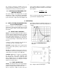
Fig. 9. System for Measuring Amplifier and Detector
Noise Resolution.
Fig. 10. Noise as a Function of Bias Voltage.
d. Set the pulser Pulse Height control at the
energy of the alpha particles striking the
detector (e.g., set the dial at 547 divisions for a
5.47-MeV alpha particle energy).
e. Turn on the pulser and use its Normalize control
and attenuators to set the output due to the
pulser for the same pulse height as the pulse
obtained in step c. Lock the Normalize control
and do not move it again until recalibration is
required.
The pulser is now calibrated; the Pulse Height dial
reads directly in MeV if the number of dial divisions
is divided by 100.
AMPLIFIER NOISE AND RESOLUTION
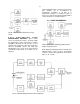
MEASUREMENTS As shown in Fig. 9, a
preamplifier, amplifier, pulse generator,
oscilloscope, and wide-band rms voltmeter such as
the Hewlett-Packard 3400A are required for this
measurement. Connect a suitable capacitor to the
input to simulate the detector capacitance desired.
To obtain the resolution spread due to amplifier
noise:
a. Measure the rms noise voltage (E
rms
) at the
amplifier output.
b. Turn on the 419 precision pulse generator and
adjust the pulser output to any convenient
readable voltage, E
o
, as determined by the
oscilloscope.
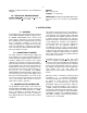
The full-width-half-maximum (FWHM) resolution
spread due to amplifier noise is then
where E
dial
is the pulser dial reading in MeV, and
2.35 is the factor for rms to FWHM. For average-
responding voltmeters such as the Hewlett-Packard
400D, the measured noise must be multiplied by
1.13 to calculate the rms noise.
The resolution spread will depend on the total input
capacitance, because the capacitance degrades the
signal-to-noise ratio much faster than the noise.
DETECTOR NOISE-RESOLUTION
MEASUREMENTS The measurement just
described can be made with a biased detector
instead of the external capacitor that would be used
to simulate detector capacitance. The resolution
spread will be larger because the detector
contributes both noise and
capacitance to the input. The detector noise-
resolution spread can be isolated from the amplifier
noise spread if the detector capacitance is known,
since
(N
det
)
2
+ (N
elec
)
2
= (N
total
)
2
,
where N
total
is the total resolution spread, and N
elec
is the electronic resolution spread when the detector
is replaced by its equivalent capacitance.
The detector noise tends to increase with bias
voltage, while the detector capacitance decreases.
The net change in resolution spread will depend
upon which effect is dominant. Figure 10 shows
curves of typical noise-resolution spread versus
bias voltage using data from several ORTEC silicon
surface-barrier semi-conductor radiation detectors.
AMPLIFIER NOISE-RESOLUTION
MEASUREMENTS USING MCA Probably the
most convenient method of making resolution
measurements is with a pulse height analyzer, as
shown by the setup illustrated in Fig. 11.