
Service manual


8
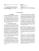
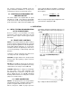
Fig. 6. Typical Waveforms Illustrating Pole-Zero
Adjustment Effects; Oscilloscope Trigger,
Internal Pos.,
60
Co Source with 1.33-MeV Peak
Adjusted ~9 V; Count Rate 3 kHz; Shaping Time
Constant 1.5
s.
OUTPUTS
UNI Front panel BNC connector with Z
o
<1 and
rear panel connector with Z
o
= 93 . Short-circuit
proof; full-scale linear range of 0 to +10 V; active
filter shaped; dc-restored with dc level adjustable to
±25 mV.
BI Front panel BNC connector with Z
o
< 1 and
rear panel connector with Z
o
= 93 . Short-circuit
proof; positive lobe leading and full-scale linear
range of 0 to +10 V; active filter shaped.
PREAMP POWER Rear panel standard ORTEC
power connector (Amphenol 17-10090) mates with
captive and noncaptive power cords on all ORTEC
preamplifiers.
4.4. STANDARD SETUP PROCEDURE
a.
Connect the detector, preamplifier, high-voltage
power supply, and preamplifier into a basic
system and connect the amplifier output to an
oscilloscope. Connect the preamplifier power
cable to the Preamp connector on the 575A rear
panel. Turn on power in the bin and power
supply and allow the electronics of the system to
warm up and stabilize.
b. Set the 575A controls initially as follows:
Shaping 1.5
s
Coarse Gain 10
Fine Gain 5.00
Pos/Neg Match input pulse
polarity
c. Use a
60
Co calibration source; place it about
25 cm from the active face of the detector. The
unipolar output pulse from the 575A should be
about 8 to 10 V using a preamplifier with a
conversion gain (charge sensitivity) of
170 mV/MeV.
d. Readjust the Gain control so that the higher
peak from the
60
Co source (1.33 MeV) provides
an amplifier output at ~9 V.
4.5. POLE-ZERO ADJUSTMENT
The pole-zero adjustment is extremely critical for
good performance at high count rates. This
adjustment should be checked carefully for the best
possible results.
USING A GERMANIUM SYSTEM AND
60
Co
a. Adjust the radiation source count rate beween
2 kHZ and 10 kHz.
b. Observe the unipolar output with an
oscilloscope. Adjust the PZ ADJ control so that
the pulse trailing edges return to the baseline
without overshoot or undershoot (Fig. 6).
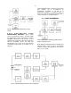
The oscilloscope used must be dc coupled and
must not contribute distortion in the observed
waveforms. Oscilloscopes such as Tektronix 453,
454, 465, and 475 will overload for a 10-V signal
when the vertical sensitivity is <100 mV/cm. To
prevent overloading the oscilloscope, use the clamp
circuit shown in Fig. 7.