
Service manual


7
o
V
cps
Rate
10000125
max
×=
τ
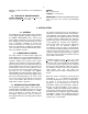
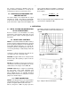
Fig. 4. Typical Unipolar and Bipolar Output
Waveforms.
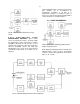
Fig. 5. Settings for Time-Constant Jumpers.
For customer convenience, ORTEC stocks the
proper terminators and BNC tees, or they can be
ordered from a variety of commercial sources.
3.7. SHORTING OR OVERLOADING THE
AMPLIFIER OUTPUT
The 575A output is dc-coupled with an output
impedance of ~0.2
. If the output is shorted with
a direct short circuit, the output stage will limit the
peak current of the output so that the amplifier will
not be harmed. When the amplifier is terminated
with 100
, the maximum count rate consistent with
linear output is
where V
o
is the peak output pulse amplitude in volts
(V) and
is the shaping time in s.
4. OPERATION
4.1. INITIAL TESTING AND OBSERVATION
OF PULSE WAVEFORMS
Refer to Section 5 for information on testing
performance and observing waveforms at front
panel test points. Figure 4 shows typical output
waveforms.
4.2. FRONT PANEL CONTROLS
GAIN A Coarse Gain switch and a Gain control (a
precision 10-turn locking potentiometer) select and
precisely adjust the gain factor for the amplification
in the 575A. Switch settings are ×2, 4, 10, 20, 40,
and 100. Continuous fine gain range is from ×0.5 to
×12.5 using markings of 500 through 1250 dial
divisions.
Using these controls collectively, the gain can be
set at any level from ×5 through ×1250.
POS/NEG A toggle switch selects an input circuit
which accepts either polarity of pulses from the
preamplifier.
PZ ADJ A screwdriver control sets the pole-zero
cancellation to match the preamplifier pulse decay
characteristics. The range is from 30
s to .
SHAPING PWB jumpers, easily accessed through
the side panel, select equal integration and
differentiation time constants to shape the input
pulses. Settings are 0.5, 1.5, and 3
s. Illustrated
drawings and instructions for setting time-constant
jumpers are shown in Fig. 5.
4.3. PANEL CONNECTORS
INPUTS Accept input pulses to be shaped and/or
amplified by the 575A. Compatible characteristics;
positive or negative with rise time from 10 to
650 ns; decay time >30
s for proper pole-zero
cancellation; input linear amplitude range 0 to 2 V
with a maximum limit of ±20 V. Input impedance is
~1000
.