
Service manual


6
3.4. CONNECTION OF TEST PULSE
GENERATOR
THROUGH A PREAMPLIFIER The satisfactory
connection of a test pulse generator (such as the
ORTEC 419 Precision Pulse Generator or
equivalent) depends primarily on two
considerations: the preamplifier must be properly
connected to the unit as discussed in Section 3.3,
and the proper input signal simulation must be
applied to the preamplifier. To ensure proper input
signal simulation, refer to the instruction manual for
the particular preamplifier being used.
DIRECTLY INTO THE 575A Since the input of the
575A has 1000-
input impedance, the test pulse
generator will normally have to be terminated at the
amplifier input with an additional shunt resistor. In
addition, if the test pulse generator has a dc offset,
a large series isolating capacitor is also required
because the 575A input is dc coupled. The ORTEC
test pulse generators are designed for direct
connection. When any one of these units is used, it
should be terminated with a 100-
terminator at the
amplifier input or be used with at least one of the
output attenuators set at In. (The small error due to
the finite input impedance of the amplifier can
normally be neglected.)
SPECIAL CONSIDERATIONS FOR POLE-ZERO
CANCELLATION When a tail pulser is connected
directly to the amplifier input, the PZ ADJ should be
adjusted if overload tests are to be made (other
tests are not affected). See Section 4.5 for the pole-
zero adjustment. If a preamplifier is used and a tail
pulser is connected to the preamplifier test input,
similar precautions are necessary. In this case the
effect of the pulser decay must be removed; that is,
a step input should be simulated.
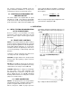
3.5. SHAPING CONSIDERATIONS
The shaping time constant on the 575A is
selectable by PWB-mounted jumpers in steps of
0.5, 1.5, and 3
s. The choice of the proper shaping
time constant is generally a compromise between
operating at a shorter time constant for
accommodation of high counting rates and
operating with a longer time constant for a better
signal-to-noise ratio. For scintillation counters, the
energy resolution depends largely on the scintillator
and photomultiplier, and therefore a shaping time
constant of about four times the decay-time
constant of the scintillator is a reasonable choice
(for Nal, a 1.5
s shaping time constant is about
optimum). For gas proportional counters, the
collection time is normally in the 0.5 to 5
s range
and a 1.5
s or greater time constant selection will
generally give optimum resolution. For surface
barrier semiconductor detectors, a 0.5
to 2 s
resolving time will generally provide optimum
resolution. Shaping time for Ge(Li) detectors will
vary from 1.5 to 6
s, depending on the size,
configuration, and collection time of the specific
detector and preamplifier. When a charge-sensitive
preamplifier is used, the optimum shaping time
constant to minimize the noise of a system can be
determined by measuring the output noise of the
system and dividing it by the system gain. The
575A has almost constant gain for all shaping
modes; therefore, the optimum shaping can be
determined by measuring the output noise with a
voltmeter as each shaping time constant is
selected.
3.6. LINEAR OUTPUT CONNECTIONS
AND TERMINATING CONSIDERATIONS
Since the 575A unipolar output is normally used for
spectroscopy, the unit is designed with the flexibility
to interface the pulse with an analyzer. A gated
baseline restorer (BLR) circuit is included in this
output for improved performance at all count rates.
The threshold for the restorer gate is determined
automatically, according to the input noise level.
The unipolar output dc level is 0 to ± 5 mV. Three
general methods of termination are used. The
simplest of these is shunt termination at the
receiving end of the cable. A second method is
series termination at the sending end. The third is a
combination of series and shunt termination, where
the cable impedance is matched both in series at
the sending end and in shunt at the receiving end.
The combination is most effective, but this reduces
the amount of signal strength at the receiving end
to 50% of that which is available in the sending
instrument.
To use shunt termination at the receiving end of the
cable, connect the output from the 575A front or
rear panels through 93-
cable to the input of the
receiving instrument. Then use a BNC tee
connector to attach both the interconnecting cable
and a 100-
terminator at the input connector of
the receiving instrument. Since the input
impedance of the receiving instrument is normally
1000
or more, the effective instrument input
impedance with the 100-
terminator will be of the
order of 93
, and this will match the cable
impedance correctly.