Online UPS PowerWalker 6000C LCD / PowerWalker 10000C LCD PowerWalker VFI 6000C/R LCD / PowerWalker VFI 10000C/R LCD Manual (EN) Uninterruptible Power Supply System EN
EN Please comply with all warnings and operating instructions in this manual strictly. Save this manual properly and read carefully the following instructions before installing the unit. Do not operate this unit before reading through all safety information and operating instructions carefully.
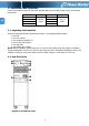
Table of Contents 1. SAFETY AND EMC INSTRUCTIONS ................................................................................................................... 3 1-1. TRANSPORTATION AND STORAGE ............................................................................................................................. 3 1-2. PREPARATION ................................................................................................................................................... 3 1-3.
1. Safety and EMC instructions Please read carefully the following user manual and the safety instructions before installing the unit or using the unit! 1-1. Transportation and Storage EN Please transport the UPS system only in the original package to protect against shock and impact. The UPS must be stored in the room where it is ventilated and dry. 1-2. Preparation Condensation may occur if the UPS system is moved directly from cold to warm environment.
1-4. Operation Do not disconnect the earth conductor cable on the UPS or the building wiring terminals in any time since this would cancel the protective earth of the UPS system and of all connected loads. The UPS system features its own, internal current source (batteries). The UPS output sockets or output terminal blocks may be electrically live even if the UPS system is not connected to the building wiring outlet.
2. Installation and Operation EN There are two different types of online UPS: standard and long-run models. Please refer to the following model table. Model Type Model Type 6K 6KL 6KR 6KRL Standard Long-run model model 10K 10KL 10KR 10KRL 2-1. Unpacking and Inspection Unpack the package and check the package contents.
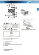
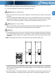
EN Diagram 2: 6KL/10KL Rear Panel Diagram 3: 6K(L)/10K(L) Input/Output Terminal Diagram 4: 6KR(L)/10KR(L) Rear Panel Diagram 5: Rack Input/Output Terminal Diagram 6: Rack Battery Pack Rear Panel 1. External battery connector 2. RS-232 communication port 3. Intelligent slot 4. USB communication 5. Emergency power off function connector (EPO connector) 6. Cooling fan 7. Input circuit breaker 8. Input/Output terminal (Refer to Diagram 3 and 5 for the details) 9. Maintenance bypass switch 10.
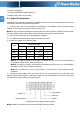
11. Grounding terminal 12. Utility input terminal 13. External maintenance bypass switch port 14. Battery pack output circuit breaker EN 2-3. Single UPS Installation Installation and wiring must be performed in accordance with the local electric laws/regulations and execute the following instructions by professional personnel. 1) Make sure the mains wire and breakers in the building are in compliance with the standard of rated capacity of UPS to avoid the hazards of electric shock or fire.
NOTE 2: Please install the output breaker between the output terminal and the load, and the breaker should be qualified with leakage current protective function if necessary. 6) Put the terminal block cover back to the rear panel of the UPS. Warning: (Only for standard model) EN ● Make sure the UPS is not turned on before installation. The UPS should not be turned on during wiring connection. ● Do not try to modify the standard model to the long-run model.
● Make sure the protective earth ground wiring is correct. The current spec, color, position, connection and conductance reliability of wire should be checked carefully. ● Make sure the utility input & output wiring is correct. The current spec, color, position, connection and conductance reliability of wire should be checked carefully. Make sure the L/N terminal is correct, not reverse or short-circuited. EN 2-4.
3. Operations 3-1. Button Operation Button Function ON/Enter Button Turn on the UPS: Press and hold the button more than 0.5s to turn on the UPS. Enter Key: Press this button to confirm the selection in setting menu. OFF/ESC Button Turn off the UPS: Press and hold the button more than 0.5s to turn off the UPS. Esc key: Press this button to return to last menu in setting menu. Test/Up Button Mute/Down Button Test/Up + Mute/Down Button Battery test: Press and hold the button more than 0.
LCD Panel: EN Display Function Backup time information Indicates the backup time in numbers. H: hours, M: minutes, S: seconds Fault information Indicates that the warning and fault occurs. Indicates the fault codes, and the codes are listed in details in section 3-9. Mute operation Indicates that the UPS alarm is disabled. Output & Battery voltage information Indicates the output voltage, frequency or battery voltage.
Battery information Indicates the Battery capacity by 0-25%, 26-50%, 51-75%, and 76-100%. EN Indicates the battery is fault. Indicates low battery level and low battery voltage. Input & Battery voltage information Indicates the input voltage or frequency or battery voltage. Vac: Input voltage, Vdc: battery voltage, Hz: input frequency 3-3.
3-4. Single UPS Operation 1. Turn on the UPS with utility power supply (in AC mode) EN 1) After power supply is connected correctly, set the breaker of the battery pack at “ON” position (the step only available for long-run model). Then set the input breaker at “ON” position. At this time the fan is running and the UPS supplies power to the loads via the bypass. The UPS is operating in Bypass mode.
3) Make sure the battery numbers setting on the control board (Please refer to the section 3-4-12 for detailed setting) is consistent to real connection. 4) The charging current can be changed from 0.5A to 6A via LCD or software. Please make sure that the charging current is suitable to battery specification. 5. Battery mode operation 1) When the UPS is in Battery mode, the buzzer will beep according to different battery capacity.
10. Operation in warning status 1) When Fault LED flashes and the buzzer beeps once every second, it means that there are some problems for UPS operation. Users can get the fault code from LCD panel. Please check the trouble shooting table in chapter 4 for details. EN 2) Some warning alarms can’t be muted unless the error is fixed. Please refer to section 3-3 for the details. 11.
NCF Normal mode (not CVCF mode) CF CVCF mode SUB Subtract ADD Add ON On OFF Off FBD Not allowed OPN Allow RES Reserved EN 3-6. LCD Setting There are three parameters to set up the UPS. Refer to following diagram. Parameter 1: It’s for program alternatives. Refer to below table for the programs to set up. Parameter 1 Parameter 2 and parameter 3 are the setting options or values for each program. Note: Please select “Up” or “Down” button to change the programs or parameters.
19 Battery capacity and groups setting 20 Backup time calibration *Y means that this program can be set in this mode.
04: Frequency range for bypass Interface Setting Parameter 2: Set the acceptable low frequency for bypass. 50 Hz system: Setting range is from 46.0Hz to 49.0Hz. 60 Hz system: Setting range is from 56.0Hz to 59.0Hz. The default value is 46.0Hz/56.0Hz. Parameter 3: Set the acceptable high frequency for bypass. 50 Hz: Setting range is from 51.0Hz to 54.0 Hz. 60 Hz: Setting range is from 61.0Hz to 64.0Hz. The default value is 54.0Hz/64.0Hz.
09: Battery maximum discharge time setting Interface EN 10: reserved Interface Setting reserved 12: reserved Interface Setting reserved 11: reserved Interface Setting Parameter 3: 000~999: Set the maximum discharge time from 0min to 999min. UPS will shut down to protect battery after discharge time arrives. The default value is 990min. DIS: Disable battery discharge protection and backup time will depend on battery capacity.
14: Charger voltage adjustment Interface 15: Inverter voltage calibration Interface Setting reserved 17: reserved Interface Setting Parameter 2: you may choose Add or Sub to calibrate inverter voltage Parameter 3: the voltage range is from 0V to 6.4V, the default value is 0V. 16: reserved Interface Setting Parameter 2: you may choose Add or Sub to adjust charger voltage Parameter 3: the voltage range is from 0V to 6.4V, the default value is 0V.
19: Battery capacity and groups setting Interface Setting Parameter 2: Set the battery capacity such as 7AH, 9AH, 10AH, 12AH, 17AH, 26AH, 40AH, 65AH, 100AH and so on. The default value is 9AH. Parameter 3: Set battery group range from 1 to 6. The default value is 1 group. These parameters are for the battery backup time calculation EN 20: Backup time calibration Interface Setting Parameter 3: Calibrate the displayed backup time by adjusting this multiplier factor.
Battery mode Description When the input voltage is beyond the acceptable range or power failure, UPS will backup power from battery and alarm will beep every 4 seconds. LCD display EN Bypass mode Description When input voltage is within acceptable range and bypass is enabled, turn off the UPS and it will enter Bypass mode. Alarm beeps every two minutes. LCD display Battery Test Description When UPS is in AC mode or CVCF mode, press “Test” key for more than 0.5s.
3-9.
4. Trouble Shooting If the UPS system does not operate correctly, please solve the problem by using the table below. Symptom Possible cause Remedy No indication and alarm in the front The AC input power is not Check if input cable firmly display panel even though the mains is connected well. connected to the mains. normal. The icon and the warning code flash on LCD display and alarm beeps every second. EPO function is enabled. The icon and flash on LCD display and alarm beeps every second.
5. Storage and Maintenance 5-1. Storage Before storing, charge the UPS at least 7 hours. Store the UPS covered and upright in a cool, dry EN location. During storage, recharge the battery in accordance with the following table: Storage Temperature Recharge Frequency Charging Duration -25°C - 40°C Every 3 months 1-2 hours 40°C - 45°C Every 2 months 1-2 hours 5-2. Maintenance The UPS system operates with hazardous voltages. Repairs may be carried out only by qualified maintenance personnel.
6. Specifications PowerWalker PowerWalker VFI 6000 6000C/R LCD 6000 VA / 4800 W MODEL CAPACITY* INPUT 110 VAC ± 3 % at 50% Load; 176 VAC ± 3 % at 100% Load Low Line Loss Voltage + 10V 300 VAC ± 3 % High Line Loss Voltage - 10V 46Hz ~ 54 Hz @ 50Hz system 56Hz ~ 64 Hz @ 60Hz system Single phase with ground ≧ 0.