
User's Manual

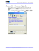
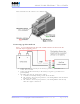
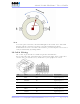
Table Of Contents
- _
- FCC Compliance and Industry Canada Statement
- Liability Notice
- Safety
- Chapter 1: Package Contents
- Chapter 2: Product Description
- Introduction
- Modem Views
- _
- Summary of Specifications
- Indicators Lights (LED)
- Data Interface Specifications: Serial, USB, Ethernet
- General Purpose Input and Outputs Specifications
- Power Specifications
- Chapter 3: BlueVue Device Manager
- Chapter 4: Wireless WAN Setup
- Chapter 5: LAN Setup
- Chapter 6: IP Networking Features
- Chapter 7: Serial IP – Packet Assembly Disassembly
- Chapter 8: GPS Settings
- Chapter 9: IO Management
- Chapter 10: Event Reporting
- Chapter 11: Firmware Upgrade
- Chapter 12: Hardware Installation
- Appendix A: Warranty and Support

4000/5000 Modems’ User Guide
Test
To test the power connection, check the PWR light on the modem: if it is turned ON
then the modem is powered. If it’s OFF, review the installation procedures.
If LED indicators are not accessible to the installer a personal computer can be used to
verify it’s functionality by running BVDM.
IO Cable Wiring
The 15-foot 10-pin IO cable is available for purchase from BlueTree.
On one end of the cable is the Molex plug as shown in the figure below, on the other
end, the wires are stripped for easy connection to your equipment or sensors.
Pin Color Label Description
1 BLUE DI3 Digital Input #3
2 ORANGE DI1 Digital Input #1
3 GREEN O1 Digital Output #1
4 BROWN AI3 (4600/5600 only) Analog Input #3
5 GRAY AI1 Analog Input #1
6 VIOLET DI4 Digital Input #4
Revision 1.0 Copyright © 2004-2006 BlueTree Wireless Data Inc. Page 42 of 44