
User's Manual

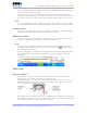
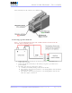
Table Of Contents
- _
- FCC Compliance and Industry Canada Statement
- Liability Notice
- Safety
- Chapter 1: Package Contents
- Chapter 2: Product Description
- Introduction
- Modem Views
- _
- Summary of Specifications
- Indicators Lights (LED)
- Data Interface Specifications: Serial, USB, Ethernet
- General Purpose Input and Outputs Specifications
- Power Specifications
- Chapter 3: BlueVue Device Manager
- Chapter 4: Wireless WAN Setup
- Chapter 5: LAN Setup
- Chapter 6: IP Networking Features
- Chapter 7: Serial IP – Packet Assembly Disassembly
- Chapter 8: GPS Settings
- Chapter 9: IO Management
- Chapter 10: Event Reporting
- Chapter 11: Firmware Upgrade
- Chapter 12: Hardware Installation
- Appendix A: Warranty and Support

4000/5000 Modems’ User Guide
Pin designations for the connector are shown below.
Powering up the modem
Note: It is recommended to have the cellular antenna connected to the
modem before applying power.
Connect the red wire directly to the battery’s positive (+) terminal or to a
source of 8-to-30Vdc
Connect the black wire directly to the battery’s negative (-) terminal or to
ground (GND)
The white wire must be connected to either:
a. A switch for manually turning on and off the modem
b. The vehicle’s “Accessory for position 2”, for turning ON the modem without
turning on the engine
c. The vehicle’s “Accessory for position 3”, for turning ON the modem only
when the engine is turned on.
Revision 1.0 Copyright © 2004-2006 BlueTree Wireless Data Inc. Page 41 of 44