
User's Manual
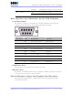
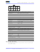

Table Of Contents
- _
- FCC Compliance and Industry Canada Statement
- Liability Notice
- Safety
- Chapter 1: Package Contents
- Chapter 2: Product Description
- Introduction
- Modem Views
- _
- Summary of Specifications
- Indicators Lights (LED)
- Data Interface Specifications: Serial, USB, Ethernet
- General Purpose Input and Outputs Specifications
- Power Specifications
- Chapter 3: BlueVue Device Manager
- Chapter 4: Wireless WAN Setup
- Chapter 5: LAN Setup
- Chapter 6: IP Networking Features
- Chapter 7: Serial IP – Packet Assembly Disassembly
- Chapter 8: GPS Settings
- Chapter 9: IO Management
- Chapter 10: Event Reporting
- Chapter 11: Firmware Upgrade
- Chapter 12: Hardware Installation
- Appendix A: Warranty and Support

4000/5000 Modems’ User Guide
Pin
number
Name Description
1 GND Ground
2 POS Power supply input 8 to 30 Vdc
3 IGN Ignition sense input – turns ON/OFF the modem
4 O3 Digital Output 3
O3 IGN
GND POS
Power input to the modem is protected against reverse polarity and over-
voltage.
The POS input is also monitored by the modem as a dedicated analog input.
The IGN input is also monitored by the modem as a dedicated digital input.
Current consumption
Active mode:
Æ the modem is in a call and is transmitting or receiving data
Average of 169mA @ PCS 1900Mhz (Peak: 286 mA)
Average of 154mA @ Cellular 800Mhz (Peak: 268 mA)
Idle mode:
Æ the modem is either not in a call, or is in one but is Dormant
Æ Dormant is the state the modem is in after 20sec of inactivity
49mA
Ignition OFF:
Æ the modem is turned OFF but still has power from its POS input
Æ all circuitry is shutdowns except for Non-Volatile memory and Real Time Clock
1mA
Revision 1.0 Copyright © 2004-2006 BlueTree Wireless Data Inc. Page 13 of 44