
User's Manual
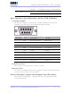
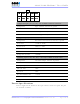
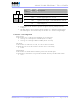

Table Of Contents
- _
- FCC Compliance and Industry Canada Statement
- Liability Notice
- Safety
- Chapter 1: Package Contents
- Chapter 2: Product Description
- Introduction
- Modem Views
- _
- Summary of Specifications
- Indicators Lights (LED)
- Data Interface Specifications: Serial, USB, Ethernet
- General Purpose Input and Outputs Specifications
- Power Specifications
- Chapter 3: BlueVue Device Manager
- Chapter 4: Wireless WAN Setup
- Chapter 5: LAN Setup
- Chapter 6: IP Networking Features
- Chapter 7: Serial IP – Packet Assembly Disassembly
- Chapter 8: GPS Settings
- Chapter 9: IO Management
- Chapter 10: Event Reporting
- Chapter 11: Firmware Upgrade
- Chapter 12: Hardware Installation
- Appendix A: Warranty and Support

4000/5000 Modems’ User Guide
3x Digital Outputs (O1, O2, O3) – O3 available on Power connector
Configuration Open Collector, reference to ground
Absolute Maximum IDC 500mADC (Vce = 750mVDC)
Absolute Maximum VDC 30VDC (open circuit)
Absolute Minimum VDC 0.4VDC (open circuit)
4x Digital Inputs (DI1, DI2, DI3, DI4)
Configuration Non-isolated level detection, reference to ground
Active level 1.6VDC to 30VDC
Inactive level 0VDC to 1.3VDC
Absolute Minimum VDC 0.3VDC
Absolute Maximum VDC 33VDC
Leakage IDC at 5VDC 150uADC
3x Analog Inputs (AI1, AI2, AI3) – AI3 only available on 4600/5600
Configuration Not isolated input, reference to ground
Resolution 1024 (ADC 10-bit)
VDC per step 4.8875855mVDC
Full scale level 5VDC
Zero level 0VDC
Absolute Minimum VDC -0.3VDC
Absolute Maximum VDC 8.3VDC
Leakage IDC at 5VDC 265.96 uADC TYPE
Power Specifications
Power is supplied to the modem via the 4-pin connector on the rear panel. The pins
are described as follows:
Revision 1.0 Copyright © 2004-2006 BlueTree Wireless Data Inc. Page 12 of 44