
User's Manual
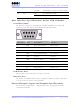
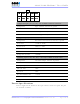

Table Of Contents
- _
- FCC Compliance and Industry Canada Statement
- Liability Notice
- Safety
- Chapter 1: Package Contents
- Chapter 2: Product Description
- Introduction
- Modem Views
- _
- Summary of Specifications
- Indicators Lights (LED)
- Data Interface Specifications: Serial, USB, Ethernet
- General Purpose Input and Outputs Specifications
- Power Specifications
- Chapter 3: BlueVue Device Manager
- Chapter 4: Wireless WAN Setup
- Chapter 5: LAN Setup
- Chapter 6: IP Networking Features
- Chapter 7: Serial IP – Packet Assembly Disassembly
- Chapter 8: GPS Settings
- Chapter 9: IO Management
- Chapter 10: Event Reporting
- Chapter 11: Firmware Upgrade
- Chapter 12: Hardware Installation
- Appendix A: Warranty and Support

4000/5000 Modems’ User Guide
Flashing Transmitting/receiving data from network
OFF No position fix available GPS GPS
Flashing Once for every GPS message received
Data Interface Specifications: Serial, USB, Ethernet
Serial Port (DB9)
The modem’s serial port is an RS232 DCE, compliant with EIA-232 standard. The
connector used is DB9 female and is shown in the illustration below.
Pin number Name Description Direction
1 DCD Data Carrier Detect Modem to PC
2 RXD Receive Data Modem to PC
3 TXD Transmit Data PC to Modem
4 DTR Data Terminal Ready PC to Modem
5 GND Ground Common
6 DSR Data Set Ready Modem to PC
7 RTS Request To Send PC to Modem
8 CTS Clear To Send Modem to PC
9 RI Ring Indicator Modem to PC
USB Device Port
This is a USB2.0 Device interface on a Type B connector.
Ethernet Port
The modem 10/100Mbps Ethernet port is compliant to EIA-568 standard, and requires
a crossover cable to connect to host terminals.
General Purpose Input and Outputs Specifications
The modem has 4 digital inputs, 3 digital outputs and 3 analog inputs for remote
control and monitoring.
Revision 1.0 Copyright © 2004-2006 BlueTree Wireless Data Inc. Page 11 of 44