
User's Manual


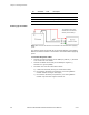


Table Of Contents
- FCC Compliance and Industry Canada Statement
- January 2005
- Chapter 1: Introduction
- Chapter 2: Product Description
- Available Models
- Front View
- Rear View
- Top View
- Bottom View
- LED indicators
- Serial Port (DB9)
- USB Port (Type B)
- Ethernet Port (RJ-45)
- Input and Output Ports (Digital & Analog I/O)
- Power Connector
- Chapter 3: Installation Requirements
- Cellular antenna
- GPS antenna
- Serial cable
- Ethernet cable
- USB cable
- Power source
- Mounting Hardware
- Wireless network account
- Chapter 4: Installing the Modem
- Power cable connector
- Powering up the modem
- Adding the modem
- Creating the DUN profile
- Chapter 5: Troubleshooting
- Appendix A: Warranty and Customer Support

Chapter 4: Installing the Modem
28 BlueTree Wireless BT4400 & BT5400 Product Manual V0.0
Powering up the modem
Note: Make sure that the antenna is connected to the modem before applying
power.
The ignition Sense Line should not be connected directly to the battery.
Make sure that the antenna is connected to the modem before applying
power
To connect the power cable:
• Connect the red wire directly to the battery’s positive (+) terminal
or to a source of 8-to-30Vdc.
• Connect the black wire directly to the battery’s negative (-)
terminal or to ground (GND).
• The white wire must be connected to either:
a) a switch for manually turning on and off the modem,
b) the vehicle’s “Accessory for position 2”, for turning ON the
modem without turning on the engine,
c) the vehicle’s “Accessory for position 3”, for turning ON the
modem only when the engine is turned on.
Pin Annotation Color Description
1 GND Black Ground
2 POS Red Power supply input 5 to 30 Vdc
3 IGN White Ignition input
4 OUT Green Not used
The Ignition Sense Line
should not be connected
directly to the battery.