
User's Manual


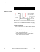


Table Of Contents
- FCC Compliance and Industry Canada Statement
- January 2005
- Chapter 1: Introduction
- Chapter 2: Product Description
- Available Models
- Front View
- Rear View
- Top View
- Bottom View
- LED indicators
- Serial Port (DB9)
- USB Port (Type B)
- Ethernet Port (RJ-45)
- Input and Output Ports (Digital & Analog I/O)
- Power Connector
- Chapter 3: Installation Requirements
- Cellular antenna
- GPS antenna
- Serial cable
- Ethernet cable
- USB cable
- Power source
- Mounting Hardware
- Wireless network account
- Chapter 4: Installing the Modem
- Power cable connector
- Powering up the modem
- Adding the modem
- Creating the DUN profile
- Chapter 5: Troubleshooting
- Appendix A: Warranty and Customer Support

Chapter 4: Installing the Modem
V0.0 BlueTree Wireless BT4400 & BT5400 Product Manual 27
5) Installing the
GPS Antenna
For BT5400 models only, follow these steps to install the GPS antenna:
1. Thread the antenna cable through the vehicle so the cable can
reach the front plate of the modem.
2. Connect the cable to the SMA connector finger tight. Do not use
tools.
6) Installing the
Power Cable
The modem includes a 15-foot power cable with 2A in-line fuse.
Power cable connector As shown below, the power cable connects to the modem through a
Molex type connector (MiniFit 4-pin).
The ignition sense line (white wire) acts as an ON/OFF power switch.
The modem will turn on when the ignition sense line is set between 8
and 30 volts DC. The modem will turn off if the ignition sense line is
less than 5 volts DC.
Pin designations for the connector are shown below.
Connect the
cable here.
Connects to
modem.
Connects to
12 volt DC
power supply.