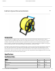
0/10/2018 Fathom Spool Documentation Fathom Spool Documentation Introduction The Fathom Spool is a rugged and easy to use tether spool for the Fathom and Fathom Slim ROV tethers. With an integrated slip ring, adjustable drag brake and secure locking cable connectors, it’s quick to set up and use in a variety of conditions. Full IP67 water resistance means water splashes are no problem, and a reversible locking handle makes it easy to transport.
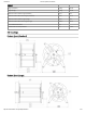
10/10/2018 Fathom Spool Documentation Physical Weight (Standard) 2.22Kg 4.89 lbs Weight (Large) 2.89 Kg 6.38 lbs Maximum Fathom Tether Length (Standard) 150 m 492 ft Maximum Fathom Slim Tether Length (Standard) 540 m 1772 ft Maximum Fathom Tether Length (Large) 300 m 984 ft Maximum Fathom Slim Tether Length (Large) 1080 m 3543 ft Dust and Water Resistance IP67 Included Cable to FXTI Topside Box 8m 26.25 ft 2D Drawings Fathom Spool (Standard) Fathom Spool (Large) http://docs.
10/10/2018 Fathom Spool Documentation 3D Model All 3D models are available on GrabCAD in the following le types: SolidWorks Part (.sldprt) IGES (.igs) STEP (.step) STL (.stl) Fathom Spool Fathom Spool (Standard) (https://grabcad.com/library/blue-robotics-fathom-spool-standard-1) Fathom Spool (Large) (https://grabcad.com/library/blue-robotics-fathom-spool-large-1) Assembly Introduction The Fathom Spool kit comes at packed and requires about one hour of assembly time.
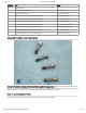
10/10/2018 Fathom Spool Documentation Quantity Part Usage 1 Crank Handle (black plastic) 6 Spool stando (blue anodized aluminum, standard or large) 1 Frame handle (blue anodized aluminum, standard or large) 2 Frame feet (black anodized aluminum, standard or large) 1 Slip ring core (black anodized aluminum assembly) 1 8m tether extension cable (yellow) 1 Crank arm thumbscrew (black anodized aluminum) 6 Foot bumper (black rubber) 2 8” Velcro cable tie 1 Black plastic plug 2 1/4-20 Bl
10/10/2018 Fathom Spool Documentation Quantity Part Usage 1 Black plastic plug 2 1/4-20 Black nylon thumbscrew Spool braking 3 White nylon cable clamps Spool tether clamping 8 M5x12 button head cap screw (316 stainless steel) Spool ange construction 12 M5x16 button head cap screw (316 stainless steel) Spool ange construction 3 8-1/2” thread forming screw (316 stainless steel) Cable clamp mounting 4 M3x6 button head cap screw (316 stainless steel) Slip ring cap ange retention 4 4-5/
10/10/2018 Fathom Spool Documentation For the standard version, with a 2.5 mm hex driver use two threadlocked M4x10 screws to attach two rubber feet to the bottom of each frame foot. Repeat to make two units. For the large version, with a 2.5 mm hex driver use three threadlocked M4x10 screws to attach three rubber feet to the bottom of each frame foot. Step 2: Assembling the First Frame Half http://docs.bluerobotics.
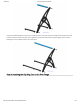
10/10/2018 Fathom Spool Documentation Using six threadlocked M4x20 screws and a 2.5 mm hex driver, screw the two feet and single frame handle to the same side of a side panel, rubber feet point down. Tighten the screws until they indent the plastic slightly. Note the round handle goes to the rounded tip at the top of the frame. Step 3: Attaching the Slip Ring Core to the First Flange http://docs.bluerobotics.
10/10/2018 Fathom Spool Documentation Use four threadlocked M5x12 screws and a 3.0 mm hex driver to attach the slip ring core to a ange. Note the screw heads come through the plastic ange to screw into the aluminum slip ring core, and the long end of the core should be passed through the central hole in the ange. Tighten the screws until they indent the plastic slightly. Step 4: Adding the Spool Stando s For the standard version, use six threadlocked M5x12 screws and a 3.
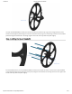
10/10/2018 Fathom Spool Documentation For the large version, use six threadlocked M5x16 screws instead and a 3.0 mm hex driver to secure the six spool stando s and one sti ening ring, with the sti ening ring placed between the stando s and the spool face. Match the sti ening ring cutout pattern to the spool face. Tighten the screws until they indent the plastic slightly. Step 5: Attaching the Crank Arm Hub to the Second Flange Using four threadlocked M5x12 screws and a 3.
/10/2018 Fathom Spool Documentation For the standard version, use three #8-1/4” self tapping screws and a #2 Phillips head driver to secure three nylon clamps the inside face of the ange where the plug is located. The clamps should be mounted next to each other in the second from outermost holes. For the large version, use three #8-1/2” self tapping screws instead and a #2 Phillips head driver to secure the clips against the face of the sti ening ring.
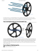
10/10/2018 Fathom Spool Documentation Attach the two anges to each other with six threadlocked M5x12 screws, locating the stando s in the outermost ring of holes. Use two 3.0mm hex drivers, one on each side of the assembly, to tighten each pair of screws per stando in sequence. Tighten the screws until they indent the plastic slightly. Step 8: Completing the Frame http://docs.bluerobotics.
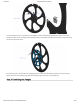
10/10/2018 Fathom Spool Documentation Mount the spool assembly to the partially assembled rst frame half, and then use six threadlocked M4x20 screws and a 2.5 mm hex driver to capture the assembly by completing the frame with the second frame panel. The spool assembly can be mounted in either orientation so that the crank handle can be on either side according to personal preference. Pictured is the left handed cranking orientation. Note the round handle goes to the rounded tip at the top of the frame.
10/10/2018 Fathom Spool Documentation Secure the slip ring core with the blue slip ring cap ange, attaching with four #4-5/8” self tapping screws and a #1 Pillips head driver on the outer holes to the plastic frame, and four threadlocked M3x6 screws with a 2.5 mm hex driver on the inner holes to the aluminum slip ring core. The slip ring core should be oriented such that the white strip on the Binder 770 connector faces up as much as possible.
10/10/2018 Fathom Spool Documentation Use two M4x20 screws and a 2.5 mm hex driver to secure the crank handle to the crank arm. The crank arm can curve to either direction according to aesthetic preference. DO NOT use threadlocker. Step 12: Attaching the Crank DO NOT use threadlocker for this step. Use the aluminum thumbscrew to attach the crank to the crank hub to complete your Fathom Spool. No threadlock is needed, the thumbscrew is designed to be removeable. http://docs.bluerobotics.
10/10/2018 Fathom Spool Documentation Mounting the Tether A Binder 770 connector is required on the topside end of your tether to enable use with the Fathom Spool. If your tether does not have a Binder 770 connector installed, refer to the Binder 770 Installation Tutorial (/binder770/). Step 1: Preparing the Connector http://docs.bluerobotics.
10/10/2018 Fathom Spool Documentation Rotate the locking collar on the tether Binder 770 connector to line up the white vertical arrow with the rounded tooth on the interior. This puts the connector in the unlocked position. Step 2: Loosening the Tether Clips http://docs.bluerobotics.
10/10/2018 Fathom Spool Documentation Loosen the three white tether retaining clips so they easily swing up. Step 3: Guiding in the Tether Pass the tether to the interior of the spool between two of the blue stando s just ahead of the tether retaining clips. Step 4: Securing the Connection Connect the tether to the slip ring core, rotating the locking collar to lock the connector in place.
10/10/2018 Fathom Spool Documentation Inspect and clean the contacts of the Binder 770 connectors if necessary. Every 100 Hours of Operation or Every 6 Months Check the operation and condition of the sealing x-ring in the slip ring core. If there is signi cant resistance or rough running, inspect with the following steps: 1. Loosen the connector on the outside of the unit to break the seal and open an air vent. 2.
10/10/2018 http://docs.bluerobotics.