
Data Sheet

LX200V20 Powerline Module
6
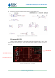
LX200V20 Homeplug AV Powerline Module
8
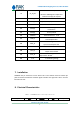
ZC_IN_EX
Zero Cross Input.
Minimun:100mVpp,AC coupled and
Maximum:3.3Vpp,AC coupled
9
GPIO[0]
RED_LED, System Link
10
GPIO[1]
GRE_LED(Green),System Self check
11
GND
Ground
12
GPIO[2]
Ethernet ACT LED: Shining when data in
transmission
13
GPIO[3]
Factory Default
14
VDD2P0
Ethernet Ethernet 2.0V
15
PERX_P
Differential In. Positive Differential Input
from Bandpass filter
16
PERX_N
Differential In. Negative differential
Input from Bandpass filter
17
GND
Ground
18
PETX_P
Differential Out. Positive Differential
output of the TX PGA
19
PETX_N
Differential Out. Negative Differential
output of the TX PGA
20
3.3V
+3.3V Working voltage
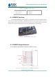
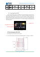
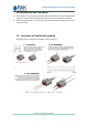
7. Installation
LX200V20 has pin connector to main board. This is the common dual row 2.0mm pin
pitch connectors for Ethernet and other signals interface. The right side is Pin”1” and the
left side is Pin”20”.
8. Electrical Characteristics
Table 3 LX200V20 Electrical Specification
Min.
Typical
Max.