
Data Sheet

LX200V20 Powerline Module
5
LX200V20 Homeplug AV Powerline Module
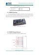
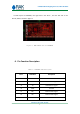
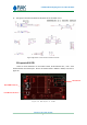
In PCB Layout of LX200V20, the right side is the Pin”1”, and the left side is the
Pin”20”,which is shown in figure 3.
Figure 3 PCB LAYOUT Size Of LX200V20
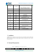
6. Pin Function Description
Table 2 LX200V20 Pin Description
Pin #
Definition
Description
1
GND
Ground
2
TX+
Powerline Tx signal
3
TX-
Powerline Tx signal
4
GND
Ground
5
RX+
Power line Rx signal
6
RX-
Power line Rx signal
7
GND
Ground