
Data Sheet
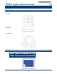

TSYS01 Digital Temperature Sensor
TSYS01 Rev 11 www.meas-spec.com 2013-03
2/10
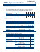
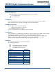
ABSOLUTE MAXIMUM RATINGS
Absolute maximum ratings are limiting values of permitted operation and should never be
exceeded under the worst possible conditions either initially or consequently. If exceeded by
even the smallest amount, instantaneous catastrophic failure can occur. And even if the
device continues to operate satisfactorily, its life may be considerably shortened.
Parameter
Symbol
Conditions
Min
Typ
Max
Unit
Supply Voltage
VDD
-0.3
+3.6
V
Operating Temperature
Top
-40
+125
°C
Storage temperature
Tstor
-55
+150
°C
ESD rating
ESD
Human Body Model (HBM)
pin to pin incl. VDD & GND
-4
+4
kV
Humidity
Hum
Non condensing
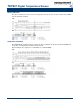
OPERATING CONDITIONS
Parameter
Symbol
Conditions
Min
Typ
Max
Unit
Operating Supply Voltage
V
DD
stabilized
2.2
3.6
V
High Accuracy Supply Voltage
V
DD
To achieve Acc1
3.2
3.4
V
Supply Current
I
DD
1 sample per second
12.5
µA
Standby current
IS
No conversion, VDD = 3V
T = 25°C
T = 85°C
0.02
0.70
0.14
1.40
µA
µA
Peak Supply Current
I
DD
During conversion
1.4
mA
Conversion time
T
CONV
7.40
8.22
9.04
ms
Serial Data Clock SPI
F
SCLK
20
MHz
Serial Data Clock I
2
C
F
SCL
400
kHz
VDD Capacitor
Place close to the chip
100nF
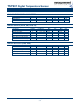
OPERATIONAL CHARACTERISTICS
If not otherwise noted, 3.3V supply voltage is applied.
Parameter
Symbol
Conditions
Min
Typ
Max
Unit
Temp. Measurement Range
T
RANG
-40
125
°C
Accuracy 1
T
ACC1
-5°C < T < +50°C
V
DD
= 3.2V – 3.4V
-0.1
+0.1
°C
Accuracy 2
T
ACC2
-40°C < T < +125°C
V
DD
= 3.2V – 3.4V
-0.5
+0.5
°C
Power Supply Reject Ratio
PSRR
V
DD
= 2.7 – 3.6
T = 25°C, C = 100nF
0.2
°C
Temperature Resolution
T
RES
0.01
°C
Time Constant
T
liquid
t
63
(t
1
t
2
)
t
1
= 25°C (air 0m/s)
t
2
= 75°C (liquid)
PCB 900mm
2
x 1.5mm FR4
3
s
T
air
t
63
(t
1
t
2
)
t
1
= 25°C (air 0m/s)
t
2
= 75°C (air stream 60m/s)
PCB 900mm
2
x 1.5mm FR4
4
s
Self Heating
SH
1
10 samples/s, 60s, still air
0.02
°C