
IM-FAH-Dowflow-0672327-00

8
REINSTALLING IN DOWNFLOW CONFIGURATION (CONT.)
IMPORTANT
Increase blower speed on all models for downflow
operation.
WARNING
Electric shock hazard! - Disconnect all power
supplies before servicing.
Replace all parts and panels before operating.
Failure to do so can result in death or electrical
shock.
3-Speed PSC Motor
1. For downflow operation, use the next highest speed
setting available.
2. If set to high speed from the factory, use high speed for
downflow.
3. Refer to the air handler installation instructions for details
on how to change the blower speed.
5-Speed High Efficiency ECM Motor
1. If factory-set speed tap 3 is desirable for your application,
use speed tap 5 for downflow.
2. If speed tap 2 is desirable for your application, use speed
tap 3 in downflow.
3. Refer to the air handler installation instructions for details
on how to change the blower speed.
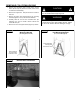
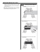
FIGURE 17
Downflow Configuration
Access Panel Removed
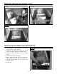
Insulated Downflow Coil Support
Insulated Front Air Seal
Outer Coil Slab Shields
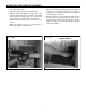
Wrap the Suction Manifold
with Insulating Foam Tape
to Prevent Condensation
from Forming
Factory-Insulated
Drain Pan Drip Shields
Evaporator Coil in
Downflow Configuration
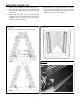
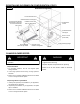
Blower Panel
Supply (Discharge) Flange
Plenum
#8-18x1˝ Screws
(3 Each Side)
Insulated Downflow
Coil Support
Insulated Rear
Air Seal
CHANGE BLOWER SPEED