
IM-FAH-Dowflow-0672327-00

6
MODIFYING AIR HANDLER HOUSING
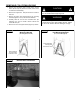
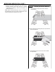
1. Turn housing upside down.
2. Reinstall the support bar using 4 screws (Figure 11)
3. Sizes 18 & 24 Units Only: Use three strips of the
provided insulated tape (Part I) and attach to exposed
side of the blower housing (Figure 12). This is required
only for these sizes to prevent sweating in downflow.
NOTE: Removing the blower housing to perform this task is
optional.
NOTE: If the insulated tape covers the wiring diagram, an
additional wiring diagram is included in the kit,
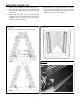
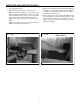
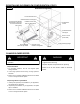
4. Using the two insulated coil support brackets (Part B and
six #8-18 x 1” screws (Part F) provided in the downflow
kit, install the coil supports brackets to the inner sides of
the cabinet (Figures 13 and 14).
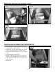
5. Position the front and rear insulated air seals (part E)
onto the downflow coil support brackets (Figure 15). Be
sure the seals seat against the back and front of the air
handler and that the front will seat against the access
panel when reinstalled.
FIGURE 11 FIGURE 12
Blower Housing Insulated
(Sizes 18 & 24)
Installing Support Bar