
BPHP14 Heat Pump Package Unit Installation Manual


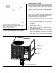


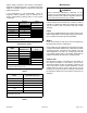

Table Of Contents

507296-01B Page 5 of 13Issue 1650
Duct System
Duct system should be designed and sized according to the
methods in Manual Q of the Air Conditioning Contractors of
America (ACCA).
A closed return duct system shall be used. This shall not
preclude use of economizers or outdoor fresh air intake. It
is recommended that supply and return duct connections
at the unit be made with exible joints.
The supply and return air duct systems should be designed
for the CFM and static requirements of the job. They
should not be sized to match the dimensions of the
duct connections on the unit.
The unit is shipped ready for horizontal ow (side duct
connections). Before attaching side ducts, bend perforated
duct tabs out to assist with duct alignment and attachment.
Duct attachment screws are intended to go into the duct
panel. Duct to unit connections must be sealed and
weather proofed.
If downow duct system is desired, a downow conversion
kit is required, and the following conversion is required.
1. Using a knife, cut following the marked cut lines on
the unit base insulation to access bottom metal covers
underneath the insulation.
2. Remove the screws securing the bottom covers and
discard the bottom covers (supply and return).
3. Remove screws located between the supply and return
openings that attach the blower deck to the base, and
discard these screws. These screws can interfere with
bottom duct connections or roof curb seals.
4. Secure side duct covers provided in the downow
conversion kit over the side duct openings (use
dimples on back panel to locate cover attachments).
5. Install drain pan overow switch and wire according to
downow conversion kit instructions.
Filters
Air lters are not supplied with the unit. A eld-provided air
lter must always be installed ahead of the evaporator coil
and must be kept clean or replaced. Dirty lters will reduce
the airow of the unit.
An optional lter rack kit may be purchased separately
for installation inside the unit’s coil compartment. Air lter
sizes are shown in Table 2 for use with lter rack kit.
The lter rack must be installed prior to installation of
the unit in applications where access to the rear panel
is limited.
NOTE:
Table 2. Unit Air Filter Sizes - inches
Unit Model Filter 1 Filter 2
24,30,36 14 X 20 20 X 20
42,48,60 20 X 20 20 X 20
Condensate Drain
This package unit is equipped with a 3/4” FPT coupling
for condensate line connection. Plumbing must conform
to local codes. Use a sealing compound on male pipe
threads.
Do not operate unit without a drain trap. The condensate
drain is on the negative pressure side of the blower;
therefore, air being pulled through the condensate line will
prevent positive drainage without a proper trap.
The condensate drain line must be properly trapped,
routed to a suitable drain and primed prior to unit
commissioning.
NOTE: Install drain lines and trap so they do not block
service access to the unit.
See Figure 5 for proper drain arrangement. The drain line
must pitch to an open drain or pump to prevent clogging
of the line. Seal around the drain connection with suitable
material to prevent air leakage into the return air system.
To prime trap, pour several quarts of water into drain,
enough to ll drain trap and line.
Drain lines should be hand-tightened only. Do not use
tools to tighten tting into drain.
CAUTION