
BPGE14 Gas Electric Package Unit Installation Manual

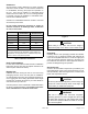


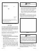
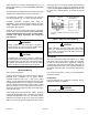
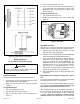
Table Of Contents

507295-01B Page 3 of 14Issue 1810
Clearances
All units require certain clearances for proper operation
and service. Refer to Table 1 for the minimum clearances
to combustibles, servicing, and proper unit operation. In
the U.S., units may be installed on combustible oors
made from wood or class A, B, or C roof covering material.
In Canada, units may be installed on combustible oors.
Units must be installed outdoors.
Clearance to combustibles below the unit ue is 10 inches
since the ue points down.
Do not permit overhanging structures or shrubs to
obstruct condenser air discharge outlet, combustion
air inlet, or vent outlet.
Table 1. Minimum Clearances
Clearance to
Combustibles
Clearance for
Service Access
Front of unit 0 in. 24 in.
Back of unit 0 in. 0 in.
Left side 0 in. 24 in.
Right side (from
vent hood)
12 in. 24 in.
Base of unit 0 in. 0 in.
Top of unit 0 in. 48 in.
Minimum clearance to combustible material below the ue
is 10 inches to allow proper dissipation of ue gasses and
temperatures. For any future service, installer must provide
access to screws of top and rear panels.
Roof Curb Installation
If a roof curb is used, follow the manufacturer’s Installation
Instructions and be sure that all required clearances are
observed (see Clearances section).
Rigging Unit
Exercise care when moving the unit. Do not remove any
packaging until the unit is near the place of installation.
An optional lifting lug kit may be purchased separately for
use in rigging the unit for lifting. Spreaders whose length
exceeds the unit depth dimension by 6 inches MUST be
used across the top of the unit.
Units may also be moved or lifted with a forklift while still in
the factory supplied packaging. The lengths of the forks
of the forklift must be a minimum of 42 inches.
Figure 1.
Before lifting a unit, make sure that the weight is
distributed equally on the cables so that it will lift evenly.
CAUTION
Unpacking
Carefully remove outer packaging material and discard.
Locate the four (4) shipping brackets that attached the
unit to the wood pallet and remove. Locate the supply duct
corner and seal the shipping openings in the base from
the underside with silicone or other approved sealant to
prevent air leakage during unit operation.
Service Access
Access to all serviceable components is provided by four
removable panels: upper access panel (for blower, ID coil,
and optional lter), heat exchanger access, control access
panel, and compressor access.
As with any Mechanical equipment, personal injury can
result from contact with sharp sheet metal edges. Be
careful when you handle this equipment.
CAUTION
This unit is charged with HFC-410A refrigerant.
Operating pressures for units charged with HFC-410A
are higher than pressures in units charged with HCFC-
22. All service equipment MUST be rated for use with
HFC-410A refrigerant.
WARNING