
Oil Furnace L85 Series Installation Manual
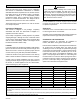
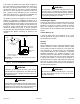
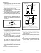
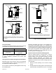
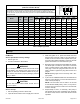
Table Of Contents

507148-01 Issue 1406 Page 3 of 13
Installation
Read all instructions before starting work so installation
will conform to Underwriters’ Laboratories or Canadian
Standards Association requirements. The furnace must be
level when placed on its foundation (upow, counterow,
and basement models) or in its suspended position
(horizontal models). Using a carpenter’s level, check the
furnace in at least two directions. The weight must be
distributed evenly before the duct work is attached.
These instructions must be placed on or near the furnace
in a conspicuous place.
Inspection of Shipment
This furnace is shipped in one package, completely
assembled and wired. The thermostat is shipped in a
separate carton when ordered.
Upon receipt of equipment, carefully inspect it for possible
shipping damage. If damage is found, it should be noted
on the carrier’s freight bill. Damage claims should be led
with the carrier immediately. Claims of shortages should
be led with the seller within 5 days.
Location
Locate the furnace as centrally as possible so that all warm
pipes to the various rooms are nearly the same length. This
allows each room to receive an equal and proper amount
of heat. This may vary with each particular installation.
Position the furnace so the pipe connection to the chimney
will be of minimum distance and have a minimum of ttings.
In utility rooms or similar installations, the door or access
opening should be large enough to permit replacement of
the furnace, or another appliance such as a water heater,
without disturbing any other equipment.
In any installation where damage from oil may occur,
a drain pan must be installed. The drain pan must be
large enough size to completely prevent any potential
oil damage. The drain pan piping must be sized to drain
the oil pump capacity and the piping must be routed to
drain the oil back to the oil tank.
WARNING
For attic installations, a booster oil pump may be required
to supply oil to the oil burner. Check state and local codes
for specic requirements.
Clearances
A minimum of 24” is recommended in front of the furnace
for servicing the burner on all models.
See Table 1 for a complete listing of the minimum clearances
required for basement type and upow installations.
Combustion and Ventilation Air
Adequate provisions for combustion air, ventilation of
furnace, and dilution of the gases must be made.
If the furnace is installed in a conned space and combustion
air is taken from the heated space, the supply air and
ventilating air must be through two permanent openings
of equal area. A conned space is “a space whose volume
is less than 50 cubic feet per 1000 BTU per hour of the
combined input rating of all appliances installed in that
space.” One opening must be within 12” of the ceiling and
the other within 12” of the oor. Each opening must have a
minimum free area of at least 1 square inch per 1000 BTU
per hour of total input rating of all appliances within the
space but not less than 100 square inches.
Basement Type Units Hi - Boy (Upow)
LBF & LBR LUF
67/87 104/118 67/87 104/118
Top of Plenum and Duct Work 2” 2” 2” 2”
Plenum Sides 3” 3” 3” 3”
Furnace Sides 6”* 6”** 0” 0”
Furnace Rear 24” 24” 0” 0”
From Front Door 4” 4” 4” 4”
Flue Pipe Clearance to Combustibles** 9” 9” 6” 6”
Type of Floor Comb. Comb. Comb. Comb.
Combustion Air Openings (2 required) 10” x 20” 11” x 22” 10” x 20” 11” x 22”
* A passage, suitable for a large person, shall be provided between the furnace and chimney for inspection or replacement of the ue
connector when necessary. A clearance of 24” shall be allowed at the rear and on one side of the furnace for service and cleaning of
the blower.
** The minimum clearance shown to the ue pipe may be reduced by using special protection permitted by local building codes and
National Fire Protection Association Standards and CSA 139.
Table 1. Minimum Clearances to Combustibles – Upow Installations