
Oil Furnace L85 Series Installation Manual
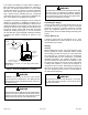
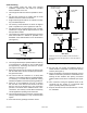
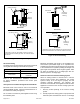
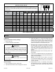
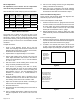
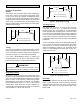
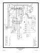
Table Of Contents

507148-01 Issue 1406 Page 11 of 13
7.5 minutes
Y
y
82%
100%
82%
1
min
CALL OFF
Y - Cool Demand Present
- Cool Demand Satisfied
y
Figure 9. Single Stage Cooling
Two Stage Cooling
See Figure 10. A call for 1st stage cooling from the
thermostat closes the R to Y1 circuit on the blower
interface board. The control waits for a 1-second delay
before energizing the circulating blower. The blower motor
runs at 57% of the selected air ow for the rst 7.5 minutes
of the 1st stage cooling demand (passive dehumidication
mode). After 7.5 minutes, the blower motor runs at 70% of
the selected cooling air ow until 1st stage cooling demand
is satised.
A call for 2nd stage cooling from the thermostat closes the
R to Y2 circuit on the blower interface board. The blower
motor ramps up to 100% of the selected cooling air ow.
When the demand for cooling is met, the blower ramps
down to Y1 until satised, then ramps down to 57% for 1
minute, then turns o.
Figure 10. Two Stage Cooling
Y1
y1
57%
100%
CALL OFF
7.5
minutes
70%
Y1 - 1 Stage Cool Demand Present
st
- Demand Satisfied1 Stage Cool
st
y1
Y2 - 2 Stage Cool Demand Present
nd
- 2 Demand Satisfied
nd
Stage Cool
y2
1
min
70%
Y1
y2
/
Y1
/
Y2
y1
57%
1
min
57%
Heat Pump
For heat pump operation, clip the jumper wire between R
and O. In heat pump mode, a call for heat pump operation
follows the same sequence as a call for cooling with the
exception that there is a 30-second blower ramp up to
blower CFM.
Operation
Sequence of Operation
Heating
See Figure 8. The thermostat calls for heat, activating the
burner motor. After a 15-second pre-purge period, power
is sent to the burner and ignition is established. When
the burner pump reaches full speed, the solenoid valve is
energized. After the thermostat is satised, the thermostat
circuit opens. The solenoid valve is de-energized before
the pump rotation stops. Power to the burner is interrupted,
shutting down the burner.
Figure 8. Heating
W
w
100%
82%
3.5 min
CALL OFF
W - Heat Demand Present
- Heat Demand Satisfied
w
13%
50%
1
min
1
min
Cooling
Unit is set up at the factory for single stage cooling. For two
stage cooling operation, the jumper wire running from Y1
to Y2 on the blower interface board must be clipped and
removed. See Figure 12 for two stage cooling wiring.
If the active dehumidication feature is enabled, the
circulating blower runs at 82% of the selected cooling
speed as long as there is a call for dehumidication.
The system must not be in either the passive or active
dehumidication mode when charging a cooling system.
IMPORTANT
Single Stage Cooling
See Figure 9. A call for cooling from the thermostat closes
the R to Y circuit on the blower interface board. The control
waits for a 1-second delay before energizing the circulating
blower to 82% of the selected cooling CFM (passive
dehumidication mode). After 7.5 minutes, the circulating
blower automatically ramps up to 100% of the selected
cooling airow. When the call for cooling is satised, the
circulating blower ramps back down to 82% of the selected
cooling airow for 1 minute, then shuts o.