
Oil Furnace L85 Series Installation Manual
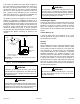
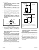
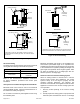
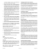
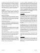
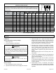
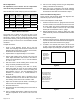
Table Of Contents

507148-01Issue 1406Page 10 of 13
Burner Adjustment
All adjustment to this furnace and its components
must be done by a qualied service technician.
Refer to Table 2 for nozzle and pump pressure information.
Furnace
Model
Burner
Head
Nozzle/
Angle
Spray
Pattern
Pump
Pressure
67* 6-SLOT .50 GPH/60 DELAVAN A 150 PSI
87* 6-SLOT .65 GPH/60 DELAVAN A 150 PSI
104 6-SLOT .75 GPH/60 DELAVAN A 145 PSI
118 6-SLOT .85 GPH/60 DELAVAN A 145 PSI
*Denotes low re bae installed. See oil burner
specications included with instructions
Table 2. Burner Information
The proper way to adjust an oil burner is with a CO2
analyzer and a smoke gun. A properly adjusted burner
will result in a quiet, clean re which will prevent sooting
and minimize cleaning. Using the following procedure will
provide a margin of reserve air to accommodate variable
conditions.
To adjust the burner:
1. Punch a 5/16” diameter service hole in the ue
outlet. This sampling hole should be at least two ue
diameters above the breech, or elbow at the breech,
but ahead of the barometric damper.
2. Operate burner for approximately 5 to 10 minutes.
3. Take a draft reading at the service hole in the ue
outlet. Adjust barometric draft control in the stack to
achieve an overre draft of –.01” to –.02” and a breach
of –.02” to –.04”.
4. Pull and record a smoke reading at the service hole
using an industry standard smoke tester.
5. If the burner is producing more than #1 smoke,
adjust the intake air using the zero setting locking
nut and adjustment screw. Loosen the locking nut
approximately one turn. Turn the adjustment screw
clockwise to increase air or counterclockwise to
decrease air.
6. Once the desired smoke level is achieved, use a
suitable test instrument for CO2 to take and record a
CO2 reading at the service hole in the ue outlet.
7. Adjust the air shutter (and air band, if necessary) to
reduce CO2 to the desired percentage.
8. Recheck smoke level.
9. Recheck draft and CO2 reading at the service hole in
the ue outlet.
10. Using a suitable thermometer, obtain and record the
ue gas temperature at the service hole in the ue
outlet.
11. Use the CO2 reading and the ue gas temperature
reading to determine unit eciency.
12. When the proper combustion and smoke readings
have been achieved, tighten the air shutter screw(s)
and air band screws that were loosened in Step 5.
Nozzle and Electrode Alignment
Proper nozzle and electrode depth and alignment are
essential for proper burner operation.
To check and adjust the nozzle depth:
1. Insert the small end of the “T” gauge into the end of the
cone and measure from the at of the end cone to the
tip of the nozzle. The proper measurement should be
1.13”. When the depth is correct, the tip of the nozzle
should just touch the base of the “T” gauge.
2. Nozzle adjustments are made by sliding the entire
nozzle assembly forward or backward within the blast
tube.
To check nozzle alignment:
1. Insert the small end of the “T” gauge into the end of the
cone and measure the nozzle and electrode alignment
against the center lines marked on the gauge.
2. If nozzle is not centered, but found to be too far left
or right, a new nozzle will need to be ordered. Do not
attempt to adjust by bending the 90° elbow in oil line.
Figure 6.
Set the NX
tip position by
aligning the
electrode top
with the mark
shown.
Set the electrode tip
gap spacing (5/32”)
by adjusting the tips
to meet the two out
side marks shown.
Make sure the tips are
centered about the
nozzle centerline.
Figure 7.