
Oil Furnace L85 Series Installation Manual
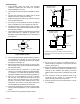
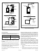
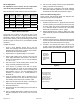
Table Of Contents

507148-01Issue 1406Page 8 of 13
To enable the continuous blower operation, place the fan
switch on the thermostat into the ON position. A call for fan
from the thermostat closes R to G on the blower interface
board. The control waits for a 1-second thermostat
debounce delay before responding to the call for fan by
ramping the circulating blower up to 50% of the cooling
speed. When the call for continuous fan is satised, the
control immediately ramps down the circulating blower.
Humidier
Terminals are provided on the control board which
provides a 120-volt output to operate a humidier. The
“HUM” terminal is energized whenever the thermostat
calls for heat. Refer to furnace wiring diagram for specic
connection information.
Electronic Air Cleaner
Terminals are provided on the control board for connection
of a 120-volt electronic air cleaner. The “EAC” terminal is
energized whenever the thermostat calls for heat, cooling,
or continuous blower. Refer to the furnace wiring diagram
for specic connection information.
Variable Speed Features
This furnace is equipped with a variable speed circulation
air blower motor that will deliver a constant airow within a
wide range of external static pressures. Other features of
this variable speed motor include:
Blower Ramp Up
The variable speed motor will slowly ramp up to normal
operating speed. This minimizes sound and increases
comfort by eliminating the initial blasts of air encountered
with standard blower motors.
Blower Ramp Down
At the end of a cooling or heating cycle, the variable
speed motor will slowly ramp down. If continuous blower
operation has been selected, the variable speed motor will
slowly ramp down to 50% of the selected cooling CFM.
Passive and Active Dehumidication
For situations where humidity control is a problem, a
dehumidication feature has been built into the variable
speed motor. At the start of each cooling cycle, the variable
speed motor will run at 82% of the rated airow for 7.5
minutes. After 7.5 minutes has elapsed, the motor will
increase to 100% of the rated airow.
To achieve additional dehumidication, remove the
dehumidify jumper located at the bottom right of the blower
interface board (see Table 3) and connect a humidity control
that opens on humidity rise to the HUM and R terminals.
The HUM terminal on the blower interface board must be
connected to the normally closed contact of the humidity
control so that the board senses an open circuit on high
humidity. In this setup, the variable speed motor will operate
at 82% of the normal cooling airow rate whenever there
is a call for dehumidication. When the relative humidity
has been brought down to an acceptable level, the cooling
blower speed will return to 100% of design.
Circulating Airow Adjustments
Cooling Mode
The units are factory set for the nominal airow for each
model. Adjustments can be made to the cooling airow
by changing the position (A, B, C, or D) of the jumper
plug on the tap marked COOL (on the blower interface
board) based on the information provided in Table 3. To
determine what CFM the motor is delivering at any time,
count the number of times the LED labeled CFM on the
blower interface board ashes. Each ash signies 100
CFM; count the ashes and multiply by 100 to determine
the actual CFM delivered (for example: 10 ashes x 100 =
1000 CFM).
Moving the jumper plug on the tap marked ADJUST from
the NORM position to the (+) or (–) position will increase or
decrease the cooling airow (Y or O call) by 15%. Changing
the position of the ADJUST jumper plug does not aect
heating airow except if a heat pump is used in conjunction
with the oil furnace. If a heat pump is used, moving the
ADJUST jumper plug to the (+) or (–) position will increase
or decrease the airow by 15% when operating in all heat
pump modes, but will not aect heating airow when the oil
furnace is used for heating.
For single stage cooling, jumper Y1 and Y2 to obtain rated
cooling CFM. In two stage cooling conguration, Y1 will
produce 70% of rated cooling CFM and Y2 will produce
100%.
Heating Mode
The unit as shipped is factory set to run at the middle of the
heating rise range as shown on the unit rating plate. The
jumper plug on the tap marked HEAT should remain in the
position (A, B, C, or D) listed in the HEAT Setting column
found in Table 3.