
Oil Furnace L85 Series Installation Manual
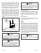
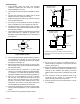
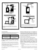
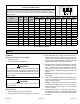
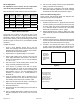
Table Of Contents

507148-01Issue 1406Page 6 of 13
Figure 4. Masonry Chimney
Rear Flue
* Barometric control may be installed in either the vertical or
horizontal section of the ue pipe within 18” of the ue outlet of
the furnace.
Cleanout
Liner
Cleanout
Cleanout
Liner
Cleanout
Barometric Control
(in either location)*
Masonry
Chimney
Masonry
Chimney
Barometric Control
(in either location)*
Front Flue
Figure 5. Horizontal Venting
Barometric
Control*
Control for
Horizontal
Venting
Barometric
Control*
Control for
Horizontal
Venting
Front Flue
Rear Flue
* Barometric control must be installed in the horizontal venting
system and located within 18” of the ue outlet of the furnace.
Horizontal Venting
The design of this furnace has been approved for horizontal
venting with the following mechanical vent systems:
Manufacturer Model
Tjernlund (sideshot SS1, SSC, SS2
Field Control
SWGII-5-SS with CK61
Control Kit
Refer to the manufacturer’s installation instructions
for proper installation procedures and service parts
information.
Vent systems are available through the local distributor.
Barometric draft control must be used in the horizontal
venting (sidewall) system. It must be located within 18” of
the furnace ue outlet (see Figure 5).
Do not common vent with any other appliance when using
the sidewall system.
Maximum permissible vent length is 100 equivalent feet,
and minimum permissible length is 15 equivalent feet.
Calculate the equivalent vent pipe footage from the furnace
to the mechanical vent system by adding the straight vent
pipe length and equivalent elbow lengths together. Each
90° elbow is equivalent to 10’ of straight pipe; each 45°
elbow is equal to 5’ of straight pipe.
Removal of Unit from Common Venting System
When an existing furnace is removed from a common
venting system serving other appliances, the venting
system is likely to be too large to properly vent the
remaining attached appliances. The following test
should be conducted with each appliance while the other
appliances connected to the common venting system are
not in operation.
1. Seal any unused openings in the common venting
system.
2. Visually inspect the venting system for proper size and
horizontal pitch and determine there is no blockage