
Oil Furnace L85 Series Installation Manual

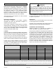


Table Of Contents

507148-01 Issue 1406 Page 9 of 13
Start-Up
Oil Burner
Burner Specication: Factory Settings
1. Burner type: NX
2. Air tube combination: NX70LHHS
Do not attempt to start the burner when excess oil has
accumulated in the chamber, when the furnace is full
of vapor, or when the combustion chamber is very hot.
Such actions could result in property damage, personal
injury, or death.
WARNING
Do not start burner unless blower access door is
secured in place.
CAUTION
Burner Start-Up
1. Set the operating control to call for heat.
2. Open all shuto valves in the oil supply line to burner.
3. While the ignition is on, press and release the reset
button (hold 1/2 second or less). If the control has not
locked out since its most recent complete heat cycle,
the lockout time will be extended to 4 minutes, and the
ignition will remain on for the entire heat cycle.
4. Bleed the pump until all froth and bubbles are purged.
The bleed port is located on the bottom of the fuel
pump. To bleed, attach a clear plastic hose over the
vent plug. Loosen the plug and catch the oil in an
empty container. Tighten the plug when all the air is
purged.
NOTE: Bleeding might not be necessary with a two-
pipe system.
5. If prime is not established within the extended lockout
time, the control will lock out. Press the reset button to
reset control (see Step 3).
NOTE: The reset button can be held for 15 seconds
for the Beckett 7505B primary control, at any time to
reset the control’s lockout counter to zero and send the
control to standby.
6. Repeat Steps 3 and 4, if necessary, until pump is
fully primed and oil is free of bubbles. Then terminate
the call for heat, and the control will resume normal
operation.
ADJUST*, HEAT, and COOL Taps
(on Blower Interface Board)
DEHUMIDIFY
CUT TO ENABLE
COOLHEATADJUST
NORM A
B
C
D
A
B
C
D
(+)
(–)
TEST
D1
* Placing ADJUST jumper plug in the TEST position energizes the motor to a default factory setting. This
can be used to determine if the motor is operating properly. Test pin function is enabled during any mode
of thermostat call. If no thermostat call is present, test function is disabled. The ADJUST jumper plug
must be returned to original position after testing procedure is completed. Failure to do so will result in
improper air ow.
Model
Motor
HP
Heat
Setting
Heating
CFM
Heating CFM @ .50 Static Cooling CFM @ .50 Static
Heat
Setting
A
Heat
Setting
B
Heat
Setting
C
Heat
Setting
D
Cool
Setting
A
Cool
Setting
B
Cool
Setting
C
Cool
Setting
D
L85UFC67V14 1/2 D 1200 1500 1400 1300 1200 1400 1200 1000 800
L85UFC87V14 1/2 A 1500 1500 1400 1300 1200 1400 1200 1000 800
L85UFC104V20 3/4 C 1550 1850 1730 1550 1400 2000 1800 1600 1200
L85UFC118V20 3/4 A 1850 1850 1730 1550 1400 2000 1800 1600 1200
L85BFC67V14 1/2 D 1200 1550 1450 1400 1200 1400 1200 1000 800
L85BFC87V14 1/2 B 1450 1550 1450 1400 1200 1400 1200 1000 800
L85BFC104V20 1 C 1550 2000 1730 1550 1450 2000 1800 1600 1200
L85BFC118V20 1 B 1730 2000 1730 1550 1450 2000 1800 1600 1200
L85BRC67V14 1/2 D 1200 1550 1450 1400 1200 1400 1200 1000 800
L85BRC87V14 1/2 A 1550 1550 1450 1400 1200 1400 1200 1000 800
L85BRC104V20 1 D 1450 2000 1730 1550 1450 2000 1800 1600 1200
L85BRC118V20 1 B 1730 2000 1730 1550 1450 2000 1800 1600 1200
Table 3. Adjusting Airow