Owner's Manual Original Instructions Cassette Type Air Conditioner Thank you for choosing our product. Please read this Owner’s Manual carefully before operation and retain it for future reference. If you have lost the Owner's Manual, please contact the local agent at 800-865-5931 or visit www.alpinehomeair.com.
BMKH12MCC BMKH18MCC
Contents 1 Safety Precautions .......................................................................................... 1 2 Outline of the Unit and Main Parts................................................................... 3 3 Operation of remote controller......................................................................... 4 3.1 Buttons on remote controller ...................................................................... 4 3.2 Introduction for icons on display screen.........................
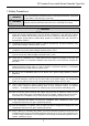
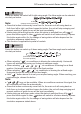
DC Inverter Free match Series Cassette Type Unit 1 Safety Precautions WARNING! This mark indicates procedures which, if improperly performed, might lead to the death or serious injury of the user. CAUTION! This mark indicates procedures which, if improperly performed, might possibly result in personal harm to the user, or damage to property. WARNING! (1) This product can’t be installed at corrosive, inflammable or explosive environment or the place with special requirements, such as kitchen.
DC Inverter Free match Series Cassette Type Unit WARNING! (14) During pump-down, stop the compressor before removing the refrigerant piping. If the compressor is still running and the stop valve is open during pump-down, air will be sucked in when the refrigerant piping is removed, causing abnormal pressure in the freezer cycle which will lead to breakage and even injury. (15) During installation, attach the refrigerant piping securely before running the compressor.
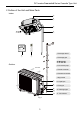
DC Inverter Free match Series Cassette Type Unit 2 Outline of the Unit and Main Parts Indoor 1 2 3 4 1. Drainage device 5 6 2. Drainage pipe Outdoor 4. Connection pipe Air inlet 5. Wired Controller 6. Wireless Controller 7. Big handle 7 8. Liquid Pipe 8 9. Gas pipe 9 10 Air outlet 11 Fig.1 3 10. Drainage pipe 11.
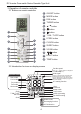
DC Inverter Free match Series Cassette Type Unit 3 Operation of remote controller 1 ON/OFF button 2 MODE button 3 FAN button 4 TURBO button 5 ▲/ ▲ 3.1 Buttons on remote controller button 6 button 1 7 button 2 8 T-ON / T-OFF button 9 I FEEL button 3 4 10 CLOCK button 5 11 SLEEP button 7 6 12 X-FAN button 9 8 13 10 13 14 11 15 12 button 14 LIGHT button 15 TEMP button 3.2 Introduction for icons on display screen { Set fan speed (No fan speed.
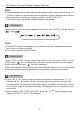
DC Inverter Free match Series Cassette Type Unit 3.3 Introduction for buttons on remote controller Note: ● This is a general use remote controller, it could be used for the air conditioners with multifunction; For some function, which the model doesn't have, if press the corresponding button on the remote controller that the unit will keep the original running status. ● After putting through the power, the air conditioner will give out a sound.
DC Inverter Free match Series Cassette Type Unit Note: ● For preventing cold air, after starting up heating mode, indoor unit will delay 1~5 minutes to blow air (actual delay time is depend on indoor ambient temperature). ● Set temperature range from remote controller: 61-86°F (16~30℃); Fan speed: auto, low speed, medium speed, high speed. 3 FAN button Pressing this button can set fan speed circularly as: auto (AUTO), low( ( ), high( ).
DC Inverter Free match Series Cassette ype Unit 6 button Press this button can select left & right swing angle. Fan blow angle can be selected circularly as below: no display (stops at current position) Note: ● Press this button continuously more than 2s, the main unit will swing back an forth from left to right, and then loosen the button, the unit will stop swinging and present position of guide louver will be kept immediately.
DC Inverter Free match Series Cassette Type Unit 8 T-ON / T-OFF button ● T-ON button "T-ON" button can set the time for timer on. After pressing this button, " " icon disappears and the word "ON" on remote controller blinks. Press "▲" or " " button to adjust T-ON setting. After each pressing "▲" or " " button, T-ON setting will increase or decrease 1min. Hold "▲" or " " button, 2s later, the time will change quickly until reaching your required time. Press "T-ON" to confirm it.
DC Inverter Free match Series Cassette Type Unit 10 CLOCK button Press this button to set clock time. " " icon on remote controller will blink. Press "▲" or " " button within 5s to set clock time. Each pressing of "▲" or " " button, clock time will increase or decrease 1 minute. If hold "▲" or " " button, 2s later, time will change quickly. Release this button when reaching your required time. ▲ ▲ ▲ Note: ● Clock time adopts 24-hour mode. ● The interval between two operations can’t exceeds 5s.
DC Inverter Free match Series Cassette Type Unit 14 LIGHT button 15 TEMP button Press this button to turn off display light on indoor unit. " " icon on remote controller disappears. Press this button again to turn on display light. " " icon is displayed. By pressing this button, you can see indoor set temperature, indoor ambient temperature or outdoor ambient temperature on indoor unit’s display.
DC Inverter Free match Series Cassette Type Unit be adjusted. ● Under energy-saving function, set temperature can’t be adjusted. Press "TURBO" button and the remote controller won’t send signal. ● Sleep function and energy-saving function can’t operate at the same time. If energy-saving function has been set under cooling mode, press sleep button will cancel energy-saving function. If sleep function has been set under cooling mode, start up the energy-saving function will cancel sleep function.
DC Inverter Free match Series Cassette Type Unit About Back-lighting Function 3.5 Operation guide 1. After putting through the power, press "ON/OFF" button on remote controller to turn on the air conditioner. 2. Press "MODE" button to select your required mode: AUTO, COOL, DRY, FAN, HEAT. 3. Press "▲" or " " button to set your required temperature. (Temperature can’t be adjusted under auto mode). 4. Press "FAN" button to set your required fan speed: auto, low speed, medium speed, high speed. 5.
DC Inverter Free match Series Cassette Type Unit 4 Preparative for Installation 4.1 Standard Accessory Parts The standard accessory parts listed below are furnished and should be used as required. Table 1 Indoor Unit Accessories No. Name Appearance Q'ty Usage To connect with the hard PVC drain pipe 1 Drain Hose 1 2 Nut with Washer 4 3 Washer 10 To be used together with the hanger bolt for installing the unit.
DC Inverter Free match Series Cassette Type Unit 4.2.1 Indoor Unit Select an installation site where the following conditions are fulfilled and that meets your customer’s approval. (1). Obstruct should be put away from the intake or outlet vent of the indoor unit so that the (2). Make sure that the installation meets the requirement of the schematic diagram of installation spaces. (3).
DC Inverter Free match Series Cassette Type Unit Table 3 Size of Fitting Pipe(Inch) Item Model Liquid BMKH12MCC BMKH18MCC 1/4'' Max. Height Max. Difference between Pipe Indoor Unit and Length Outdoor Unit (ft) (ft) Gas 3/8'' 65 49 1/2'' 65 49 Drainage pipe(Outer Diameter × wall thickness) (in) Φ25×0.059 The connection pipe should be insulated with proper water-proof insulating material. The pipe wall thickness shall be .019-.039in and the pipe wall shall be able to withstand the pressure of 6.
DC Inverter Free match Series Cassette Type Unit 5 Installation of the Unit 5.1 Installation of the Indoor Unit 5.1.1 Indoor unit dimension For the units: 12-18k H Fig.3 Table 5 Item Model BMKH12MCC BMKH18MCC A 26.37 B 26.22 C D 23.62 19.48 16 Unit: in E F 5.70 9.44 G 22.44 H 22.
DC Inverter Free match Series Cassette Type Unit 5.1.2 Installing the Main Body Unit Fig.4 (1). Install the hoisting stand on the hoisting screw by using nuts and gaskets at both the upper and lower sides of the hoisting stand. To prevent the gasket from breaking off, a gasket anchor board can be helpful. (2). (3). Adjust the unit to the best position. (4). Check if the unit is installed horizontally at four directions. If not, the water pump and the (5).
DC Inverter Free match Series Cassette Type Unit 5.1.4 Leveling The water level test must be done after installing the indoor unit to make the unit is horizontal, as shown below. Fig.8 5.2 Installation of the Connection Pipe 5.2.1 Flare Processing (1). Cut the connection pipe with the pipe cutter and remove the burrs. (2). Hold the pipe downward to prevent cuttings from entering the pipe. (3). Remove the (4). Fig.9 Fig.
DC Inverter Free match Series Cassette Type Unit 5.2.2 Bending Pipes (1). The pipes are shaped by your hands. Be careful not to collapse them. Fig.10 Pipe (2). Do not bend the pipes in an angle more than 90°. Heat insulating (3). When pipes are repeatedly bent or stretched, the material pipe will Cutter more. Do not bend or stretch the pipes more than three Cutt line times. (4). When bending the pipe, do not bend it as is. The pipe Fig.11 will be collapsed.
DC Inverter Free match Series Cassette Type Unit hand tight and then tighten it with the spanner. Refer to Table to check if the wrench has been tightened properly (too tight would mangle the nut and lead to leakage). Examine the connection pipe to see if it leaks, then take the treatment of heat insulation, as shown in the Fig.12. Use the medium-sized sponge to insulate the coupler of the gas pipe. Fig.
DC Inverter Free match Series Cassette Type Unit 5.2.4 Connecting the Pipe at the Outdoor Side Unit connector. The tightening method is the same as that as at the indoor side. 5.2.5 Checking the Pipe Connections for Gas Leaking For both indoor and outdoor unit side, check the joints for gas leaking by the use of a gas leakage detector without fail when the pipes are connected. Fig.13 5.2.
DC Inverter Free match Series Cassette Type Unit If the outdoor unit is installed higher than the indoor unit (See Fig.16) (1). Taping should be done from lower to the upper part. (2). All pipes are bound and taped together and also should be trapped to prevent water from returning to the room. (3). Restraint all pipes to the wall with saddles. Trap Fig.16 5.
DC Inverter Free match Series Cassette Type Unit (7). Slightly open the liquid valve and let some refrigerant go to the connection pipe to balance the pressure inside and outside of the connection pipe, so that air will not come into the connection pipe when removing the hose. Note that the gas and liquid valve can be opened fully only after the manifold valve assembly is removed. (8). Place back the caps of the liquid valve, gas valve and also the service port.
DC Inverter Free match Series Cassette Type Unit 5.4 Installation of the Drain Pipe (1). It is not allowed to connect the condensate drain pipe into waste pipe or other pipelines which are likely to produce corrosive or peculiar smell to prevent the smell from entering indoors or corrupt the unit. (2). It is not allowed to connect the condensate drain pipe into rain pipe to prevent rain water from pouring in and cause property loss or personal injury. (3).
DC Inverter Free match Series Cassette Type Unit 100 mm (3). When unifying multiple drain pipes, install the pipes as Fig.20. Select converging drain pipes whose gauge is suitable for the operating capacity of the unit.(take the cassette type unit for example) mm 0~1000mm 0~675 T-joint converging drain pipes T-joint converging drain pipes Fig.20 (4). When (5). If suction of outdoor air. Therefore, U-type water trap shall be designed on the drainage side of each indoor unit.(Fig.21) (6).
DC Inverter Free match Series Cassette Type Unit 3-way connection of drainage pipe joint Connection of drain elbow Fig.24 Connection of horizontal pipe Fig.25 Fig.26 5.4.3 Precautions When Doing Riser Piping Work (1). Make sure that heat insulation work is executed on the following 2 spots to prevent any possible water leakage due to dew condensation. 1). Connect the drain hose to the drain lift pipe, and insulate them. 2).
DC Inverter Free match Series Cassette Type Unit 5.4.4 Testing of Drain Piping Shown in the Fig.30, Add approximately 1 liter of water slowly into the drain pan and check Drain vent for repair use (plastic stopper is included) (drain the water in waterspoit by this outlet vent) Drain hose Test hole cover Test hole Above 100mm Plastic water pot (The length of the pipe should be about 100mm.) Fig.30 5.
DC Inverter Free match Series Cassette Type Unit (3). If gap still exists between ceiling and decoration panel after tightening the screws, readjust the height of the indoor unit. (Fig.33) Fig.33 (4). Fig.34 Fig.34 5.5.2 Installing the Panel (1). (2). (3). (4). (5). . Latch other two hooks. Tighten four hexagonal screws under the latches about 15mm. Adjust the panel along the direction indicated by the arrow as shown in Fig.35.
DC Inverter Free match Series Cassette Type Unit Fig.35 5.6 Electrical Wiring 5.6.1 Wiring Precautions WARNING! ① . Before obtaining access to terminals, all supply circuits must be disconnected. ② . The rated voltage of the unit is as shown as Table 4 ③ . Before turning on, verify that the voltage is within the 198~264V range(for single phrase unit) or 342~457V range (for three-phrase unit). ④ . Always use a special branch circuit and install a special receptacle to supply power to the air conditioner.
DC Inverter Free match Series Cassette Type Unit CAUTION! ① . The power source capacity must be the sum of the air conditioner current and the current of other capacity. ②. raise the voltage. 5.6.2 Electrical Wiring (1). For solid core wiring (Fig.36) 1). Cut the wire end with a wire cutter or wire-cutting pliers, then strip the insulation about 25 mm (15/16") . 2). Using a screwdriver, remove the terminal screw(s) on the terminal board. 3).
DC Inverter Free match Series Cassette Type Unit After passing the connection cord fasten it with the cord clamp.(Fig.38) WARNING! ① . Before starting work, check that power is not being supplied to the indoor unit and outdoor unit. ② . Match the terminal block numbers and connection cord colors with those of the indoor unit side. ③ . Erroneous wiring may cause burning of the electric parts. ④. ⑤ . Always fasten the outside covering of the connection cord with cord clamps.
DC Inverter Free match Series Cassette Type Unit (5). Electric wiring of indoor unit side Remove the electric box cover from the electric box sub-assy and then connect the wire. 12、18k: Power supply terminal board Seal here to avoid leakage 24k: Power supply terminal board Seal here to avoid leakage Fig.
DC Inverter Free match Series Cassette Type Unit CAUTION! ① . Tighten the power cord respectively on the terminal boards with ② . If the power supply are wired incorrectly, the air conditioner may be damaged. ③ . Connect the indoor unit connection cord properly based on the corresponding marks as shown in Fig.39. ④ . Ground both the indoor and outdoor units by attaching a ground wire. ⑤ . Unit shall be grounded in compliance with the applicable local and national codes.
DC Inverter Free match Series Cassette Type Unit Table 8 Number Error code Error 1 E1 2 E2 Indoor anti-freeze protection 3 E3 Compressor low pressure protection, refrigerant lack protection and refrigerant colleting mode 4 E4 Compressor high discharge temperature protection Compressor high pressure protection 5 E5 AC over-current protection 6 E6 Communication error 7 E7 Mode conflict 8 E8 Anti-high temperature protection 9 E9 Full water protection 10 F1 Indoor ambient tempera
DC Inverter Free match Series Cassette Type Unit (2). Instructions to the Error Indicating Lamps on the Panel of the Cassette Type Unit. Receiver "88" Display "Auto" Button Power Indicating Lamp Timer Indicating Lamp "Test" Button Fig.40 ◆ Power and ON/OFF Indicating Lamp: It goes red when the unit is powered on while it goes white when the unit is started. ◆ Timer Indicating Lamp: Timer indicator on indoor unit will be on when timer ON is set under off status and timer OFF is set under on status.
DC Inverter Series Cassette Type Unit Troubleshooting and Maintenance .1 Troubleshooting following points before repair: Table 10 Failure Possible Reasons ① . The power supply is not connected. ② . Electrical leakage of air-conditioning unit causes tripping of the leakage The unit cannot be started. switch. ③ . The operating keys are locked. ④ . The control loop has failure. ①. There is obstacle in front of the condenser. The unit operates for a while and then stops. ②. The control loop is abnormal.
DC Inverter Free match Series Cassette Type Unit 8.2 Routine Maintenance Only a qualified service person is allowed to perform maintenance. Before accessing to terminal devices, all power supply circuits must be disconnected. Do not use water or air of 122℉ or higher for cleaning air filters and outside panels. Notes: ① . Do not operate the air conditioner with the filter uninstalled, otherwise dust would come into the unit. ② . Do not remove the air filter except for cleaning.
DC Inverter Free match Series Cassette Type Unit 2. Disassemble the air inlet grille Open the air inlet grille at 45°, raise it and remove the grille. 3. Disassemble the filter screen Draw out the filter screen and remove it. Filter screen 4. Disassemble the air purifier Remove the air purifier after removing the fixed screws on it. Filtering element Support Bolt 5. Clean the filer screen Clean the filer screen by a vacuum cleaner or wash it by flashing water.