
BE5E Installation Instructions
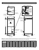
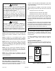
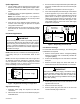
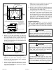
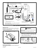
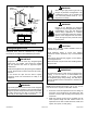
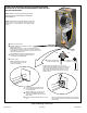
Table Of Contents
- BE5E Unit Dimensions – Upflow – Inches (mm)
- Shipping and Packing List
- General
- Requirements
- Installation Clearances
- Installation
- Condensate Drain
- Duct System and Filters
- Brazing Refrigerant Lines
- Sealing the Unit
- Electrical Connections
- Blower Performance Data
- Air Flow - Cooling Blower Speed
- Operation Inspection
- Operation
- Maintenance
- Professional Maintenance
- Cabinet Insulation
- Use of Air Handler During Construction

507788-01BIssue 1818Page 4 of 20
Excessive condensation may occur if the unit is installed
in a warm, humid place. When the unit is installed in an
unconditioned space, apply sealant around electrical
wires, refrigerant piping and condensate lines at the
point where they enter the cabinet.
Apply sealant on the inside of the cabinet at the
point where the electrical wires exit through the
conduit opening. This will also keep warm and moist
unconditioned air out of the air handler cabinet where
it will form condensate on the cooler control box and
electrical controls.
IMPORTANT
This unit is approved for installation clearance to
combustible material as stated on the unit rating
plate. Accessibility and service clearances must take
precedence over combustible material clearances.
The air handler must be installed so that free access is
allowed to the coil/lter compartment and blower/control
compartment.
IMPORTANT
NOTE: During cooling operation, excessive sweating may
occur if the air handler is installed in a warm and humid
space.
NOTE: If installed in an unconditioned space, sealant
should be applied around the electrical wires, refrigerant
tubing, and condensate lines where they enter the cabinet.
NOTE: Electrical wires should be sealed on the inside
where they exit the conduit opening. Sealant is required
to prevent air leakage into, and condensate from forming
inside of, the air handler, the control box, and on the
electrical controls.
NOTE: This unit is approved for installation clearance to
combustible material as stated on the unit rating plate.
Accessibility and service clearances must take precedence
over combustible material clearances.
NOTE: The air handler must be installed so that free
access is allowed to the coil/lter compartment and blower/
control compartment.
Louvers or return air grilles are eld-supplied. Local codes
may limit application of systems without a ducted return to
single-story buildings.
When a BE5E unit is installed in a closet with a louvered
return opening, the minimum open area for the louvers will
be:
• 320 square inches for -024 models;
• 360 square inches for -030 and -036 models;
• 450 square inches for -042 thru -060 models
If the free area is not known, assume a 25% free area for
wood or a 75% free area for metal louvers or grilles. Using
the louver dimensions and the 25% or 75% assumption,
determine if the open area meets the minimum open area
listed above.
If a return air plenum is used, the return air grille should be
immediately in front of the opening in the plenum to allow
for the free ow of return air. When not installed in front of
the opening, there must be adequate clearance around the
air handler to allow for the free ow of return air.
Installation
Each unit consists of a blower assembly, refrigerant coil,
and controls in an insulated galvanized steel factory-
nished enclosure. Knockouts are provided for electrical
wiring entrance.
For ease in installation, it is best to make any necessary
coil conguration changes before setting air handler in
place.
Refrigerant Metering Device
BE5E units are equipped with a factory-installed expansion
valve with internal check valve for cooling or heat pump
application.
HORIZONTAL DRAIN PAN
(MUST BE REMOVED)
UP-FLOW /
DOWN-FLOW
DRAIN PAN
Figure 1. Upow Conguration
Installation Clearances
Non-Ducted Return Closet Installation
The air handler can be installed in a closet with a false
bottom to form a return air plenum. It may also be installed
with a return air plenum under the air handler.