
BE5E Installation Instructions
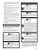
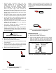
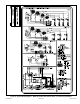
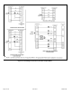
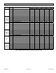
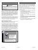
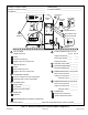
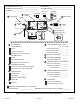
Table Of Contents
- BE5E Unit Dimensions – Upflow – Inches (mm)
- Shipping and Packing List
- General
- Requirements
- Installation Clearances
- Installation
- Condensate Drain
- Duct System and Filters
- Brazing Refrigerant Lines
- Sealing the Unit
- Electrical Connections
- Blower Performance Data
- Air Flow - Cooling Blower Speed
- Operation Inspection
- Operation
- Maintenance
- Professional Maintenance
- Cabinet Insulation
- Use of Air Handler During Construction

507788-01B Issue 1818 Page 11 of 20
3. To avoid damaging the rubber grommets in the cabinet
while brazing, slide the rubber grommets over the
refrigerant lines until they are away from the heat
source.
NOTE: Place wet rags against piping plate and around
suction line connections.
4. Connect the suction and liquid lines to the evaporator
coil. Take care to protect the cabinet and internal
components as detailed in Figure 10.
5. Braze using an alloy of silver or copper and phosphorus
with a melting point above 1,100°F (593°C).
NOTE: Do not use soft solder.
6. Allow refrigerant pipes to cool to room temperature.
NOTE: Make sure to route copper refrigerant tubing
away from sharp edges and make sure that it does
not touch other metal surfaces. This prevents damage
caused by vibration or metal-on-metal contact.
7. Reinstall the rubber grommets into the refrigerant
piping panel.
NOTE: Make sure expansion valve capillary tube is
not touching metal edges or copper tubing.
8. Make sure outdoor unit has been placed according
to the Installation Instructions and is connected to the
refrigerant lines
Sealing the Unit
Seal the unit so that warm air is not allowed into the cabinet.
Warm air introduces moisture, which results in water blow-
off problems. This is especially important when the unit is
installed in an unconditioned area.
If installed in an unconditioned space, sealant should be
applied around the electrical wires, refrigerant tubing, and
condensate lines where they enter the cabinet.
There must be an airtight seal between the bottom of
the air handler and the return air plenum. Use berglass
sealing strips, caulking, or equivalent sealing method
between the plenum and the air handler cabinet to
ensure a tight seal. Return air must not be drawn from a
room where this air handler or any gas-fueled appliance
(i.e., water heater), or carbon monoxide-producing
device (i.e., wood replace) is installed.
WARNING
Use duct tape and/ or Permagum to seal closed any
space around the holes where the drain lines exit the
cabinet. Warm air must not be allowed to enter through
any gaps or holes in the cabinet.
IMPORTANT
Electrical Connections
Electric shock hazard! - Disconnect all power
supplies before servicing.
Replace all parts and panels before operating.
Failure to do so can result in death or electrical
shock.
WARNING
Run 24V Class II wiring only through specied low
voltage opening. Run line voltage wiring only through
specied high voltage opening. Do not combine voltage
in one opening.
WARNING
Electric Shock Hazard.
Can cause injury or death.
Foil-faced insulation has conductive
characteristics similar to metal. Be sure there
are no electrical connections within 1/2ʺ of the
insulation. If the foil-faced insulation comes in
contact with electrical voltage, the foil could
provide a path for current to pass through
to the outer metal cabinet. While the current
produced may not be enough to trip existing
electrical safety devices (e.g., fuses or circuit
breakers), the current can be enough to cause
an electrical shock hazard that could cause
personal injury or death.
WARNING
Electric Shock Hazard. Can cause injury or
death. Unit must be properly grounded in
accordance with national and local codes.
Line voltage is present at all components when
unit is not in operation on units with single-
pole contactors. Disconnect all remote electric
power supplies before opening access panel.
Unit may have multiple power supplies.
WARNING
• Wiring must conform to the current National Electric
Code ANSI/NFPA No. 70, or Canadian Electric Code
Part I, CSA Standard C22.1, and local building codes.
Refer to following wiring diagrams. See unit nameplate
for minimum circuit ampacity and maximum over-
current protection size.