
BE5E Installation Instructions
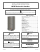
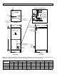
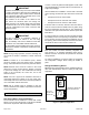
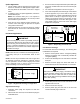
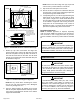
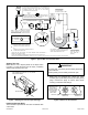
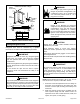
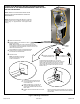
Table Of Contents
- BE5E Unit Dimensions – Upflow – Inches (mm)
- Shipping and Packing List
- General
- Requirements
- Installation Clearances
- Installation
- Condensate Drain
- Duct System and Filters
- Brazing Refrigerant Lines
- Sealing the Unit
- Electrical Connections
- Blower Performance Data
- Air Flow - Cooling Blower Speed
- Operation Inspection
- Operation
- Maintenance
- Professional Maintenance
- Cabinet Insulation
- Use of Air Handler During Construction

507788-01B Issue 1818 Page 9 of 20
BOTTOM OF
CABINET
DUCT
ADAPTER
1−1/2
(38)
”A”
BRAKE DOWN 90 DEGREES
1/4 (6) DIA.
2−HOLES
"A"
1−1/2(38)
3/4
(19)
3/4
(19)
1−1/2
(38)
3/4
(19)
1/2
(13)
3/4
(19)
DUCT
FLANGE
CABINET
DOOR FLANGE
UNIT SIZE
Cabinet and Duct Flange
-024, -030
-036, -042,
-048, -060
18-3/8"
21-1/2"
Figure 9. Cabinet and Duct Flange
Brazing Refrigerant Lines
Refrigerant lines must be connected by a qualied
technician in accordance with established procedures.
Refrigerant lines must be clean, dry, refrigerant-grade
copper lines. Air handler coils should be installed
only with specied line sizes for approved system
combinations.
Handle the refrigerant lines gently during the installation
process. Sharp bends or kinks in the lines will cause a
restriction.
Do not remove the caps from the lines or system
connection points until connections are ready to be
completed.
IMPORTANT
Polyol ester (POE) oils used with HFC-410A refrigerant
absorb moisture very quickly. It is very important that the
refrigerant system be kept closed as much as possible.
DO NOT remove line set caps or service valve stub
caps until you are ready to make connections.
WARNING
When using a high pressure gas such as
nitrogen to pressurize a refrigeration or air
conditioning system, use a regulator that
can control the pressure down to 1 or 2
psig (6.9 to 13.8 kPa).
WARNING
Danger of re. Bleeding the refrigerant
charge from only the high side may result in
pressurization of the low side shell and
suction tubing. Application of a brazing
torch to a pressurized system may result in
ignition of the refrigerant and oil mixture.
Check the high and low pressures before
applying heat.
WARNING
Brazing alloys and ux contain materials which are
hazardous to your health.
Avoid breathing vapors or fumes from brazing
operations. Perform operations only in well-ventilated
areas.
Wear gloves and protective goggles or face shield to
protect against burns.
Wash hands with soap and water after handling brazing
alloys and ux.
CAUTION
To prevent the build-up of high levels of nitrogen when
purging, it must be done in a well-ventilated area.
Purge low-pressure nitrogen (1 to 2 psig) through
the refrigerant piping during brazing. This will help to
prevent oxidation and the introduction of moisture into
the system.
IMPORTANT
NOTE: Recommended line length is 50’ or less. If more
than 50’ line set is required, contact Blue Summit.
1. Route the suction and liquid lines from the ttings on
the indoor coil to the ttings on the outdoor unit. Run
the lines in a direct path, avoiding unnecessary turns
and bends.
2. Make sure that the suction line is insulated over the
entire exposed length and that neither suction nor
liquid lines are in direct contact with oors, walls, duct
system, oor joists, or other piping.