
BE5E Installation Instructions
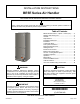
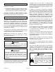
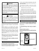
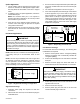
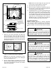
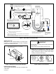
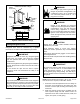
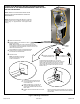
Table Of Contents
- BE5E Unit Dimensions – Upflow – Inches (mm)
- Shipping and Packing List
- General
- Requirements
- Installation Clearances
- Installation
- Condensate Drain
- Duct System and Filters
- Brazing Refrigerant Lines
- Sealing the Unit
- Electrical Connections
- Blower Performance Data
- Air Flow - Cooling Blower Speed
- Operation Inspection
- Operation
- Maintenance
- Professional Maintenance
- Cabinet Insulation
- Use of Air Handler During Construction

507788-01BIssue 1818Page 6 of 20
90º
BEND
CABINET
SUPPORT
COIL SHOWN IN UPLOAD POSITION FOR EASY CONVERSION
TOP CAP SCREWS
DRAIN PAN
REINSTALLED
HERE
DRAIN PAN
SHIPPING
LOCATION
TOP CAP ROTATED TO
CORRECT POSITION
———— DRAIN PLUGS ————
REINSTALLED HERE REMOVED FROM HERE
BACK COIL END SEAL
TOP
CAP
90º
BEND
ALIGN HOLES WITH
HOLES IN COIL END
PLATE. STARTING WITH
THE ROUND HOLES ON
THIS END.
Figure 4. Field Modication for Left-Hand Discharge
7. Rotate top cap 180º front-to-back and align with
unused screw holes. Holes must align with front and
back coil end plates. The top cap has a 45º bend on
one side and a 90º bend on the other. The 90º bend
must be on the same side as the horizontal drain pan
as illustrated in Figure 4.
FRONT EDGE OF HORIZONTAL
DRAIN PAN
Figure 5. Left-Hand Discharge Conguration
NOTE: Be very careful when reinstalling the screws
into the coil end plate engaging holes. Misaligned
screws may damage the coil.
8. From the upow position, ip cabinet 90º to the left
and set into place. Replace blower assembly. Secure
coil in place by bending down the tab on the cabinet
support rail as illustrated.
NOTE: Seal around the exiting drain pipe, liquid and
suction lines to prevent inltration of humid air.
9. Flip access door and replace it on the unit.
10. Set unit so that it is sloped 1/4ʺ toward the drain pan
end of the unit. Connect return and supply air plenums
as required using sheet metal screws.
11. If suspending the unit, it must be supported along the
entire length of the cabinet. If using chain or strap,
use a piece of angle iron or sheet metal attached to
the unit (either above or below) so that the full length
of the cabinet is supported. Use securing screws no
longer than 1/2ʺ to avoid damage to coil or lter, as
illustrated in Figure 3. Connect return and supply air
plenums as required using sheet metal screws.
Downow Application
NOTE: If downow application is required, separately
order kit number 83M57 and install per kit’s instructions.
Also use metal or class I supply and return air plenums.
Use the installation instruction provided with the downow
kit.
If electric heat section with circuit breakers (ECBA25) is
installed in a BE5E unit in a downow application, the
circuit breakers must be rotated 180° to the UP position.
See ECBA25 installation instructions for more details.
IMPORTANT
Condensate Drain
On units of this type, where the blower “draws” rather
than “blows” air through the coil, traps must be installed
in the condensate drain lines (primary and auxiliary,
if used). Traps prevent the blower from drawing air
through the drain lines into the air supply.
IMPORTANT
A eld-fabricated secondary drain pan, with a drain
pipe to the outside of the building, is required in all
installations over a nished living space or in any area
that may be damaged by overow from the main drain
pan. In some localities, local codes may require a
secondary drain pan for any horizontal installation.
IMPORTANT