
BE5E Installation Instructions
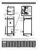
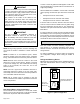
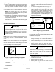
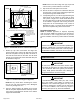
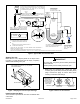
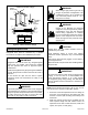
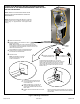
Table Of Contents
- BE5E Unit Dimensions – Upflow – Inches (mm)
- Shipping and Packing List
- General
- Requirements
- Installation Clearances
- Installation
- Condensate Drain
- Duct System and Filters
- Brazing Refrigerant Lines
- Sealing the Unit
- Electrical Connections
- Blower Performance Data
- Air Flow - Cooling Blower Speed
- Operation Inspection
- Operation
- Maintenance
- Professional Maintenance
- Cabinet Insulation
- Use of Air Handler During Construction

507788-01B Issue 1818 Page 5 of 20
Upow Application
1. The air handler must be supported on the bottom only
and set on solid oor or eld-supplied support frame.
Securely attach the air handler to the oor or support
frame.
2. If installing a unit in an upow application, remove the
horizontal drain pan.
NOTE: The horizontal drain pan is not required in
upow air discharge installations; its removal provides
the best efciency and air ow.
3. Place the unit in the desired location and slope unit.
Connect return and supply air plenums as required
using sheet metal screws.
4. Install units that have no return air plenum on a stand
that is at least 14” from the oor. This will allow proper
air return.
Horizontal Applications
When removing the coil, there is a possibility of danger
of equipment damage and personal injury. Be careful
when removing the coil assembly from a unit installed
in right- or left-hand applications. The coil may tip into
the drain pan once it is clear of the cabinet. Support the
coil when removing it..
IMPORTANT
NOTE: When the unit is installed in horizontal applications,
a secondary drain pan is recommended. Refer to local
codes.
NOTE: This unit may be installed in left-hand or right-hand
air discharge horizontal applications. Adequate support
must be provided to ensure cabinet integrity. Ensure that
there is adequate room to remove service and access
panels if installing in the horizontal position.
Drains
AIR FLOW
PLUGS
RIGHT‐HAND DRAINS
Figure 2. Right-Hand Discharge Conguration
Right-Hand Discharge
1. Determine which plugs are required for drain line
connections.
2. With access door removed, remove drain line plugs to
install drain lines.
3. Set unit so that it is sloped toward the upow drain pan
end of the unit and level from front to back of unit (see
Figure 7).
4. The horizontal conguration is shown in Figure 2.
5. If the unit is suspended, the entire length of the cabinet
must be supported. If you use a chain or strap, use a
piece of angle iron or sheet metal attached to the unit
(either above or below) to support the length of the
cabinet. Use securing screws no longer than 1/2 inch
to avoid damaging the coil or lter. See Figure 3. Use
sheet metal screws to connect the return and supply
air plenums as required.
FRONT WEIV DNEWEIV
ANGLE IRON OR SHEET
METAL
E
ANCE 4 IN. (102 MM)
MAXIMUM 1/2"
LONG SCREW
AIR FLOW
Figure 3. Suspending Horizontal Unit
Left-Hand Air Discharge
For horizontal left-hand air discharge, the following eld
modications are required.
1. Remove access panels and the corrugated padding
between the blower and coil assembly. Discard the
corrugated padding.
2. Pull the coil assembly from unit. Pull off the horizontal
drain pan.
3. Remove the drain plugs from back drain holes on
horizontal drain pan and reinstall them on front holes.
After removal of drain pan plug(s), check drain hole(s)
to verify that drain opening is fully open and free of any
debris. Also check to make sure that no debris has
fallen into the drain pan during installation that may plug
up the drain opening.
IMPORTANT
4. Rotate drain pan 180º front-to-back and install it on the
opposite side of the coil.
5. Remove screws from top cap.
6. Remove plastic plug from left hole on coil front end
seal and reinstall plug in back hole.