
BG802DF Installation Instructions
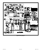
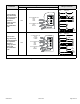
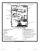
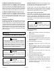
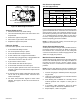
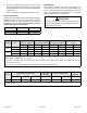
Table Of Contents
- BG802DFE Gas Furnace
- Unit Dimensions
- Parts Arrangement
- Shipping and Packing List
- Safety Information
- General
- Combustion, Dilution & Ventilation Air
- Downflow Installation
- Filters
- Duct System
- Venting
- Gas Piping
- Electrical
- Integrated Control DIP Switch Settings
- On-Board Links and Diagnostic Push Button
- Unit Start-Up
- Other Unit Adjustments
- Heating Sequence of Operation
- Service
- Repair Parts List
- Blower Performance

508145-01B Issue 2108 Page 29 of 36
Figure 24. White Rodgers Gas Valve
GAS VALVE SHOWN IN ON POSITION
INLET PRESSURE POST
HIGH FIRE
ADJUSTMENT
(under cap)
MANIFOLD
PRESSURE TAP
LOW FIRE
ADJUSTMENT
(under cap)
Turning O Gas to Unit
1. Set the thermostat to the lowest setting.
2. Turn OFF all electrical power to the unit if service is to
be performed.
3. Remove the upper access panel.
4. Move switch on gas valve to OFF. Do not force.
5. Replace the upper access panel.
Failure to Operate
If the unit fails to operate, check the following:
1. Is the thermostat calling for heat?
2. Are access panels securely in place?
3. Is the main disconnect switch closed?
4. Is there a blown fuse or tripped circuit breaker?
5. Is the lter dirty or plugged? Dirty or plugged lters will
cause the limit control to shut the unit o.
6. Is gas turned on at the meter?
7. Is the manual main shut-o valve open?
8. Is the internal manual shut-o valve open?
9. Is the unit ignition system in lock out? If the unit locks
out again, call the service technician to inspect the unit
for blockages.
10. Is pressure switch closed? Obstructed ue will cause
unit to shut o at pressure switch. Check ue and
outlet for blockages.
11. Are ame rollout switches tripped? If ame rollout
switches are tripped, call the service technician for
inspection.
Gas Pressure Adjustment
Gas Flow (Approximate)
Gas Meter Clocking Chart
Capacity
Seconds for One Revolution
Natural LP
1 cu ft
Dial
2 cu ft
Dial
1 cu ft
Dial
2 cu ft
Dial
-070 55 110 136 272
-090 41 82 102 204
Natural - 1000 btu/cu ft LP - 2500 btu/cu ft
Table 13.
Furnace should operate at least 5 minutes before checking
gas ow. Determine time in seconds for two revolutions of
gas through the meter. (Two revolutions assures a more
accurate time.) Divide by two and compare to time in Table
13. If manifold pressure matches Table 15 and rate is
incorrect, check gas orices for proper size and restriction.
Remove temporary gas meter if installed.
NOTE: To obtain accurate reading, shut o all other gas
appliances connected to meter.
Supply Pressure Measurement
An inlet post located on the gas valve provides access to
the supply pressure. See Figure 24. Back out the 3/32”
hex screw one turn, connect a piece of 5/16” tubing and
connect to a manometer to measure supply pressure. See
Table 15 for supply line pressure.
Manifold Pressure Measurement
A manifold pressure tap located on the gas valve provides
access to the manifold pressure. See Figure 24. Back out
the 3/32” hex screw one turn, connect a piece of 5/16”
tubing and connect to a manometer to measure manifold
pressure.
NOTE: Pressure test adapter kit (10L34) is available from
Blue Summit to facilitate manifold pressure measurement.
1. Connect test gauge to manifold pressure tap (Figure
24) gas valve.
2. Ignite unit on low re and let run for 5 minutes to allow
for steady state conditions.
3. After allowing unit to stabilize for 5 minutes, record
manifold pressure and compare to value given in
Table 15.
4. If necessary, make adjustments. Figure 24 shows
location of high re and low re adjustment screw.
5. Repeat steps 2, 3 and 4 on high re.