
BG802DF Installation Instructions
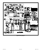
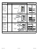
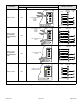
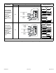
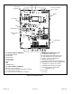
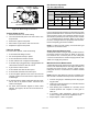
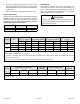
Table Of Contents
- BG802DFE Gas Furnace
- Unit Dimensions
- Parts Arrangement
- Shipping and Packing List
- Safety Information
- General
- Combustion, Dilution & Ventilation Air
- Downflow Installation
- Filters
- Duct System
- Venting
- Gas Piping
- Electrical
- Integrated Control DIP Switch Settings
- On-Board Links and Diagnostic Push Button
- Unit Start-Up
- Other Unit Adjustments
- Heating Sequence of Operation
- Service
- Repair Parts List
- Blower Performance

508145-01B Issue 2108 Page 23 of 36
Thermostat
DIP Switch Settings and On-Board Links
Wiring Connections
DIP Switch 1 On Board Links Must Be Cut To Select System Options
2 Heat / 2 Cool OFF
CUT ON-BOARD LINK
W915
2 STAGE
COMPR
T'STAT
FURNACE
TERM. STRIP
OUTDOOR
UNIT
*
*Not required on all units
2 Heat / 2 Cool
with t’stat with
dehumidication
mode
OFF
CUT ON-BOARD LINK
W915
2 STAGE
COMPR
CUT ON-BOARD LINK
W914
T'STAT
FURNACE
TERM. STRIP
OUTDOOR
UNIT
o
*
*Not required on all unit
s
2 Heat / 1 Cool
with t’stat with
dehumidication
mode
OFF
CUT ON-BOARD LINK
W914
T'STAT
FURNACE
TERM. STRIP
OUTDOOR
UNIT
o
*
* Not required on all units
2 Heat / 1 Cool OFF
DO NOT CUT ANY
ON-BOARD LINKS
T'STAT
FURNACE
TERM. STRIP
OUTDOOR
UNIT
*
*Not required on all units
NOTE - Do NOT make a wire connection between the room thermostat L terminal and the L terminal of the integrated control.
Table 9. Field Wiring for Non-Communicating Thermostat Applications