
BG802DF Installation Instructions
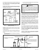

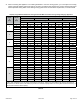
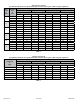
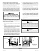
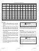
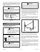

Table Of Contents
- BG802DFE Gas Furnace
- Unit Dimensions
- Parts Arrangement
- Shipping and Packing List
- Safety Information
- General
- Combustion, Dilution & Ventilation Air
- Downflow Installation
- Filters
- Duct System
- Venting
- Gas Piping
- Electrical
- Integrated Control DIP Switch Settings
- On-Board Links and Diagnostic Push Button
- Unit Start-Up
- Other Unit Adjustments
- Heating Sequence of Operation
- Service
- Repair Parts List
- Blower Performance
508145-01BPage 20 of 36 Issue 2108
Electrically ground the unit according to local codes or,
in the absence of local codes, according to the current
National Electric Code (ANSI/NFPA No. 70). A green
ground wire is provided in the eld make-up box.
NOTE: This furnace contains electronic components that
are polarity sensitive. Make sure that the furnace is wired
correctly and is properly grounded.
Accessory Terminals
One line voltage “EAC” 1/4” spade terminal is provided on
the furnace integrated control. See Figure 23 for integrated
control conguration. This terminal is energized when the
indoor blower is operating. Any accessory rated up to one
amp can be connected to this terminal with the neutral
leg of the circuit being connected to one of the provided
neutral terminals. If an accessory rated at greater than one
amp is connected to this terminal, it is necessary to use an
external relay.
One line voltage “HUM” 1/4” spade terminal is provided
on the furnace integrated control. See Figure 23 for
integrated control conguration. This terminal is energized
in the heating mode when the combustion air inducer is
operating. Any humidier rated up to one amp can be
connected to this terminal with the neutral leg of the circuit
being connected to one of the provided neutral terminals. If
a humidier rated at greater than one amp is connected to
this terminal, it is necessary to use an external relay.
Generator Use - Voltage Requirements
The following requirements must be kept in mind when
specifying a generator for use with this equipment:
• The furnace requires 120 volts ± 10% (Range: 108
volts to 132 volts).
• The furnace operates at 60 Hz ± 5% (Range: 57 Hz
to 63 Hz).
• The furnace integrated control requires both polarity
and proper ground. Both polarity and proper grounding
should be checked before attempting to operate the
furnace on either permanent or temporary power.
• Generator should have a wave form distortion of less
than 5% RHO.
Thermostat
Install the room thermostat according to the instructions
provided with the thermostat. See Table 9 for thermostat
designations. If the furnace is being matched with a
heat pump, refer to the FM21 installation instruction or
appropriate dual fuel thermostat instructions.
Indoor Blower Speeds
1. When the thermostat is set to “FAN ON,” the indoor
blower will run continuously on the low speed when
there is no cooling or heating demand. See Table 18
for allowable circulation speeds.
2. When the unit is operating in the high-re or low-
re heating mode, the indoor blower will run on the
corresponding heating speed.
3. When the unit is operating in the low cool or the high
cool cooling mode, the indoor blower will run on the
corresponding cooling speed.