
BG802DF Installation Instructions
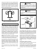
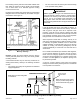

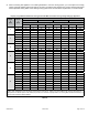
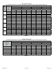
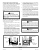
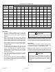
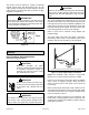

Table Of Contents
- BG802DFE Gas Furnace
- Unit Dimensions
- Parts Arrangement
- Shipping and Packing List
- Safety Information
- General
- Combustion, Dilution & Ventilation Air
- Downflow Installation
- Filters
- Duct System
- Venting
- Gas Piping
- Electrical
- Integrated Control DIP Switch Settings
- On-Board Links and Diagnostic Push Button
- Unit Start-Up
- Other Unit Adjustments
- Heating Sequence of Operation
- Service
- Repair Parts List
- Blower Performance

508145-01B Issue 2108 Page 19 of 36
The furnace must be isolated by closing its individual
manual shut-o valve and disconnecting from the gas
supply system the during any pressure testing of the gas
supply system at pressures less than or equal to 1/2 psig
(3.48 kPa, 14 inches w.c.).
When testing pressure of gas lines, gas valve must be
disconnected and isolated. See Figure 20. Gas valves
can be damaged if subjected to pressures greater than
1/2 psig (3.48 kPa, 14 inches w.c.).
IMPORTANT
Figure 20.
Electrical
ELECTROSTATIC DISCHARGE (ESD)
Precautions and Procedures
Electrostatic discharge can aect
electronic components. Take precautions
to neutralize electrostatic charge by
touching your hand and tools to metal
prior to handling the control.
CAUTION
Electric Shock Hazard. Can cause injury
or death. Unit must be properly grounded
in accordance with national and local
codes.
WARNING
Fire Hazard. Use of aluminum wire with this product
may result in a re, causing property damage, severe
injury or death. Use copper wire only with this product.
WARNING
Failure to use properly sized wiring and circuit breaker
may result in property damage. Size wiring and circuit
breaker(s) per Technical Specication and unit rating
plate.
CAUTION
The unit is equipped with a eld make-up box on the left
hand side of the cabinet. The make-up box may be moved
to the right side of the furnace to facilitate installation. If the
make-up box is moved to the right hand side, clip the wire
ties that bundle the wires together. Secure the excess wire
to the existing harness to protect it from damage.
Refer to Figure 22 for schematic wiring diagram and
troubleshooting.
The power supply wiring must meet Class I restrictions.
Protected by either a fuse or circuit breaker, select circuit
protection and wire size according to unit nameplate.
Figure 21. Interior Make-Up Box Installation
(Right Side)
MAKE-UP
BOX
Cut the two wire ties to extend power wires for right side onl
y
NOTE: Unit nameplate states maximum current draw.
Maximum over current protection allowed is 15 AMP.
Holes are on both sides of the furnace cabinet to facilitate
wiring. Install a separate (properly sized) disconnect
switch near the furnace so that power can be turned o
for servicing.
Before connecting the thermostat, check to make sure the
wires will be long enough for servicing at a later date. Make
sure that thermostat wire is long enough to facilitate future
removal of blower for service.
Complete the wiring connections to the equipment. Use
the provided unit wiring diagram shown in Figure 22. Use
18 gauge wire or larger that is suitable for Class II rating for
thermostat connections.