
BG802DF Installation Instructions
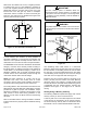
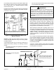

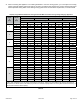
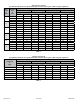
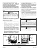
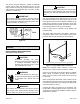

Table Of Contents
- BG802DFE Gas Furnace
- Unit Dimensions
- Parts Arrangement
- Shipping and Packing List
- Safety Information
- General
- Combustion, Dilution & Ventilation Air
- Downflow Installation
- Filters
- Duct System
- Venting
- Gas Piping
- Electrical
- Integrated Control DIP Switch Settings
- On-Board Links and Diagnostic Push Button
- Unit Start-Up
- Other Unit Adjustments
- Heating Sequence of Operation
- Service
- Repair Parts List
- Blower Performance

508145-01BPage 18 of 36 Issue 2108
Gas Pipe Capacity - FT³/HR (kL/HR)
Nominal Iron
Pipe Size -
inches (mm)
Internal
Diameter
- inches
(mm)
Length of Pipe - feet (m)
10
(3.048)
20
(6.096)
30
(9.144)
40
(12.192)
50
(15.240)
60
(18.288)
70
(21.336)
80
(24.384)
90
(27.432)
100
(30.480)
1/2
(12.7)
.622
(17.799)
172
(4.87)
118
(3.34)
95
(2.69)
81
(2.29)
72
(2.03)
65
(1.84)
60
(1.69)
56
(1.58)
52
(1.47)
50
(1.42)
3/4
(19.05)
.824
(20.930)
360
(10.19)
247
(7.00)
199
(5.63)
170
(4.81)
151
(4.28)
137
(3.87)
126
(3.56)
117
(3.31)
110
(3.11)
104
(2.94)
1
(25.4)
1.049
(26.645)
678
(19.19)
466
(13.19)
374
(10.59)
320
(9.06)
284
(8.04)
257
(7.27)
237
(6.71)
220
(6.23)
207
(5.86)
195
(5.52)
1-1/4
(31.75)
1.380
(35.052)
1350
(38.22)
957
(27.09)
768
(22.25)
657
(18.60)
583
(16.50)
528
(16.50)
488
(13.76)
452
(12.79)
424
(12.00)
400
(11.33)
1-1/2
(38.1)
1.610
(40.894)
2090
(59.18)
1430
(40.49)
1150
(32.56)
985
(27.89)
873
(24.72)
791
(22.39)
728
(20.61)
677
(19.17)
635
(17.98)
600
(17.00)
2
(50.8)
2.067
(52.502)
4020
(113.83)
2760
(78.15)
2200
(62.30)
1900
(53.80)
1680
(47.57)
1520
(43.04)
1400
(39.64)
1300
(36.81)
1220
(34.55)
1160
(32.84)
2-1/2
(63.5)
2.469
(67.713)
6400
(181.22)
4400
(124.59)
3530
(99.95)
3020
(85.51)
2680
(75.88)
2480
(70.22)
2230
(63.14)
2080
(58.89)
1950
(55.22)
1840
(52.10)
NOTE: Capacity given in cubic feet of gas per hour (kilo liters of gas per hour) and based on 0.60 specic gravity gas.
Table 8.
Gas Supply
1. This unit is shipped standard for left or right side
installation of gas piping (or top entry in horizontal
applications). Connect the gas supply to the piping
assembly.
2. When connecting the gas supply piping, consider
factors such as length of run, number of ttings, and
furnace rating to avoid excessive pressure drop. Table
8 lists recommended pipe sizes for typical applications.
3. The gas piping must not run in or through air ducts,
clothes chutes, gas vents or chimneys, dumb waiters,
or elevator shafts.
4. The piping should be sloped 1/4 inch (6.4 mm) per
15 feet (4.57 m) upward toward the meter from the
furnace. The piping must be supported at proper
intervals [every 8 to 10 feet (2.44 to 3.01 m)] with
suitable hangers or straps. Install a drip leg in vertical
pipe runs to the unit.
5. A 1/8” N.P.T. plugged tap or pressure post is located
on the gas valve to facilitate test gauge connection.
See Figure 20.
6. In some localities, codes may require the installation
of a manual main shut o valve and union (furnished
by the installer) external to the unit. The union must be
of the ground joint type.
Compounds used on threaded joints of gas piping must
be resistant to the actions of liquied petroleum gases.
IMPORTANT
NOTE: If emergency shuto is necessary, shut o the
main manual gas valve and disconnect main power to the
furnace. The installer should properly label these devices.
Leak Check
After gas piping is completed, carefully check all piping
connections (factory and eld installed) for gas leaks. Use
a leak detecting solution or other preferred means.
NOTE: If emergency shuto is necessary, shut o the main
manual gas valve and disconnect the main power to the
furnace. The installer should properly label these devices.
Some soaps used for leak detection are corrosive to
certain metals. Carefully rinse piping thoroughly after
leak test has been completed. Do not use matches,
candles, ame or other sources of ignition to check for
gas leaks.
CAUTION