
BG802DF Installation Instructions
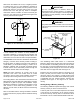
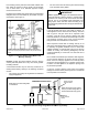

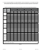
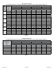
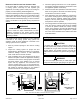
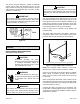

Table Of Contents
- BG802DFE Gas Furnace
- Unit Dimensions
- Parts Arrangement
- Shipping and Packing List
- Safety Information
- General
- Combustion, Dilution & Ventilation Air
- Downflow Installation
- Filters
- Duct System
- Venting
- Gas Piping
- Electrical
- Integrated Control DIP Switch Settings
- On-Board Links and Diagnostic Push Button
- Unit Start-Up
- Other Unit Adjustments
- Heating Sequence of Operation
- Service
- Repair Parts List
- Blower Performance

508145-01BPage 12 of 36 Issue 2108
When return air is drawn from a room, a negative pressure
is created in the room. If a gas appliance is operating in
a room with negative pressure, the ue products can be
pulled back down the vent pipe and into the room. This
reverse ow of the ue gas may result in incomplete
combustion and the formation of carbon monoxide gas.
This toxic gas might then be distributed throughout the
house by the furnace duct system
SUPPLY
AIR
Figure 15. Duct Installation Downow Unit
Once the venting system is installed, attach the
“Disconnected Vent” warning sticker to a visible area
of the plenum near the vent pipe. The warning sticker
is provided in the bag assembly. Order kit 66W04 for
additional stickers.
IMPORTANT
Asphyxiation hazard. The exhaust vent for this furnace
must be securely connected to the furnace ue transition
at all times.
WARNING
Figure 16.
FLUE TRANSITION
COLLAR
VENT PIPE
(min. 6” length)
“DISCONNECTED VENT”
WARNING
STICKER
FLUE
TRANSITION
COLLAR
VENT PIPE
(min. 6” length)
“DISCONNECTED VENT”
WARNING
STICKER
Use self-drilling sheet metal screws or a mechanical
fastener to rmly secure the vent pipe to the round collar of
the ue transition. If self-drilling screws are used to attach
the vent pipe, it is recommended that three be used. Drive
one self-drilling screw through the front and one through
each side of the vent pipe and collar. See Figure 16.
Install the rst vent connector elbow at a minimum of six
inches (152 mm) from the furnace vent outlet. Masonry
chimneys used to vent Category I central furnaces must
be either tile-lined or lined with a listed metal lining system
or dedicated gas vent. Unlined masonry chimneys are
prohibited. See Figure 17 and Figure 18 for common
venting.
Venting Using a Masonry Chimney
The following additional requirements apply when a lined
masonry chimney is used to vent this furnace.
A chimney with one or more sides exposed to the outside
of the structure is considered to be an exterior chimney.
An exterior masonry chimney that is not tile-lined must be
lined with B1 vent or a listed insulated exible metal vent.
Venting
A 4-inch diameter ue transition is factory-installed on
all models. Modifying or removing the ue transition will
cause the unit to operate unsafely and will void the unit
certication. The vent connector does not require insulation.
The BG802DFE series units are classied as fan-assisted
Category I furnaces when vertically vented according to
the latest edition of National Fuel Gas Code (NFPA 54
/ ANSI Z223.1). A fan-assisted Category I furnace is an
appliance equipped with an integral mechanical means
to either draw or force combustion products through the
combustion chamber and/or heat exchanger.
NOTE: Use these instructions as a guide. They do not
supersede local codes. This furnace must be vented
according to all local codes, these installation instructions,
and the provided venting tables in these instructions.
The venting tables in this manual were extracted from the
National Fuel Gas Code (NFPA 54 / ANSI Z223.1) and are
provided as a guide for proper vent installation. Proper
application, termination, construction and location of vents
must conform to local codes having jurisdiction. In the
absence of local codes, the NFGC serves as the dening
document.
Refer to the tables and the venting information contained
in these instructions to properly size and install the venting
system.