
BE5V Specifications Sheet

COMPACT AIR HANDLER
BE5V
Page 2
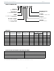
MODEL NUMBER GUIDE
M
ETERING DEVICE
4X = R410A TXV
VOLTAGE
A = 208/230V - 1PHASE - 60HZ
POSITION
M = MULTI-POSITION
TONNAGE
18, 24, 30, 36, 42, 48, 60
PRODUCT
BC= BLOWER COIL
FEATURE SET
E = ENHANCED FEATURES
SERIES
5 = 5 SERIES (1 PIECE PLATFORM,
OMNIGUARD
TM
)
MOTOR & CONTROL
C = PSC
E = CONSTANT TORQUE
V = VARIABLE SPEED
BC
E 5 V 18 M A 4X
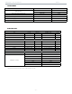
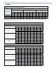
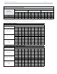
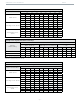
PHYSICAL
Model Volts/Hz/Phase
Max. Elec.
Heat Available
(kW)
Transformer Size
& Type
Filter Size
(in.)
Refrigerant Connection
(IDS)
Installed
TXV Size
Weight
(lbs.)
Suction
(in.)
Liquid
(in.)
BE5V18
208-230/60/1 7.5 40 VA Class 2 15 x 20 x 1 3/4 3/8 H4TXV01 109
BE5V24
208-230/60/1 10 40 VA Class 2 15 x 20 x 1 3/4 3/8 H4TXV01 127
BE5V30
208-230/60/1 15 40 VA Class 2 15 x 20 x 1 3/4 3/8 H4TXV01 133
BE5V36
208-230/60/1 15 40 VA Class 2 18 x 20 x 1 7/ 8 3/8 H4TXV02 163
BE5V42
208-230/60/1 15 40 VA Class 2 18 x 20 x 1 7/ 8 3/8 H4TXV02 168
BE5V48
208-230/60/1 20 40 VA Class 2 18 x 20 x 1 7/ 8 3/8 H4TXV02 186
BE5V60
208-230/60/1 20 40 VA Class 2 18 x 20 x 1 7/ 8 3/8 H4TXV03 186
INSTALLATION CLEARANCES WITH ELECTRIC HEAT
Cabinet 0 in. (0 mm)
To Plenum 0 in. (0mm)
To Outlet Duct within 3 ft. (914mm) 0 in. (0 mm)
Floor 0 in. (0 mm) See Note #1
Service / Maintenance See Note #2
1 Units installed on combustible floors in the downflow position with electric heat require optional downflow combustible flooring base.
2 Front service access - 24 in. (610 mm) minimum.
Note - If cabinet depth is more than 24 in. (610mm), allow a minimum of the cabinet depth plus 2 in. (51 mm).